3 Mounting and Commissioning
400
7UT613/63x Manual
C53000-G1176-C160-2
• Amplitude measurement with switched on test current:
Compare the indicated current magnitudes under measurement → secondary →
operational measured values secondary with the actually flowing values:
This applies for all measuring locations included in the test.
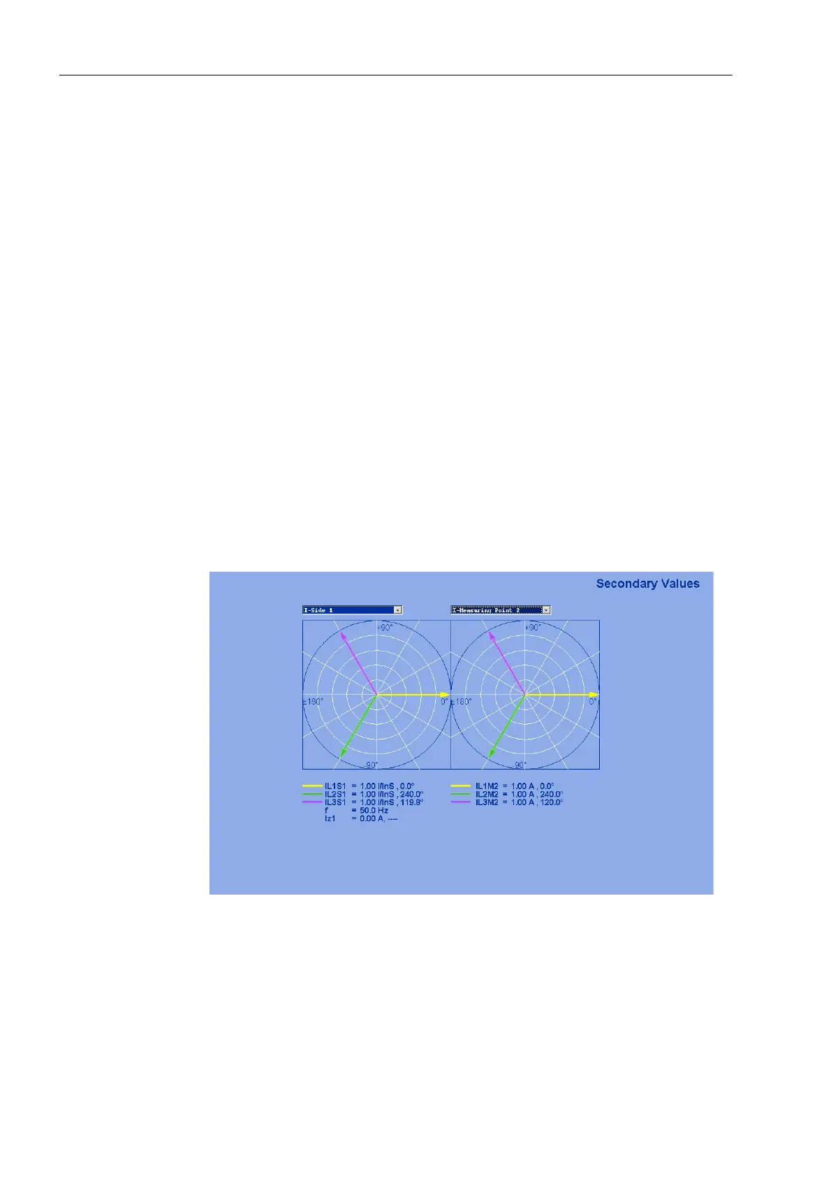
Note: The WEB Monitor provides comfortable read-out possibilities for all mea-
sured values with visualisation using phasor diagrams (Figure 3-27).
If deviations occur that cannot be explained by measuring tolerances, either a con-
nection or the test setup is wrong:
– Switch off the test source and the protected object (shut down the generator) and
earth it,
– Re-check the assignment or the tested measuring location (Section 2.1.4 under
margin heading „Assignment of 3-phase measuring locations“).
– Re-check the settings for the magnitude matching (Subsection 2.1.4 under
margin heading „Current Transformer Data for 3-phase Measuring Locations“).
– Re-check the plant connections to the device and the test arrangement and
correct them.
If a substantial zero sequence current 3I0 occurs one or two of the currents of the
corresponding side must have a reversed polarity.
3I0 ≈ phase current → one or two phase currents are missing;
3I0 ≈ double phase current → one or two phase currents with reversed polarity.
– Repeat test and re-check the current magnitudes.
Figure 3-27 Phasor Diagram of the Secondary Measured Values — Example
 Loading...


