2.1 General
53
7UT613/63x Manual
C53000-G1176-C160-2
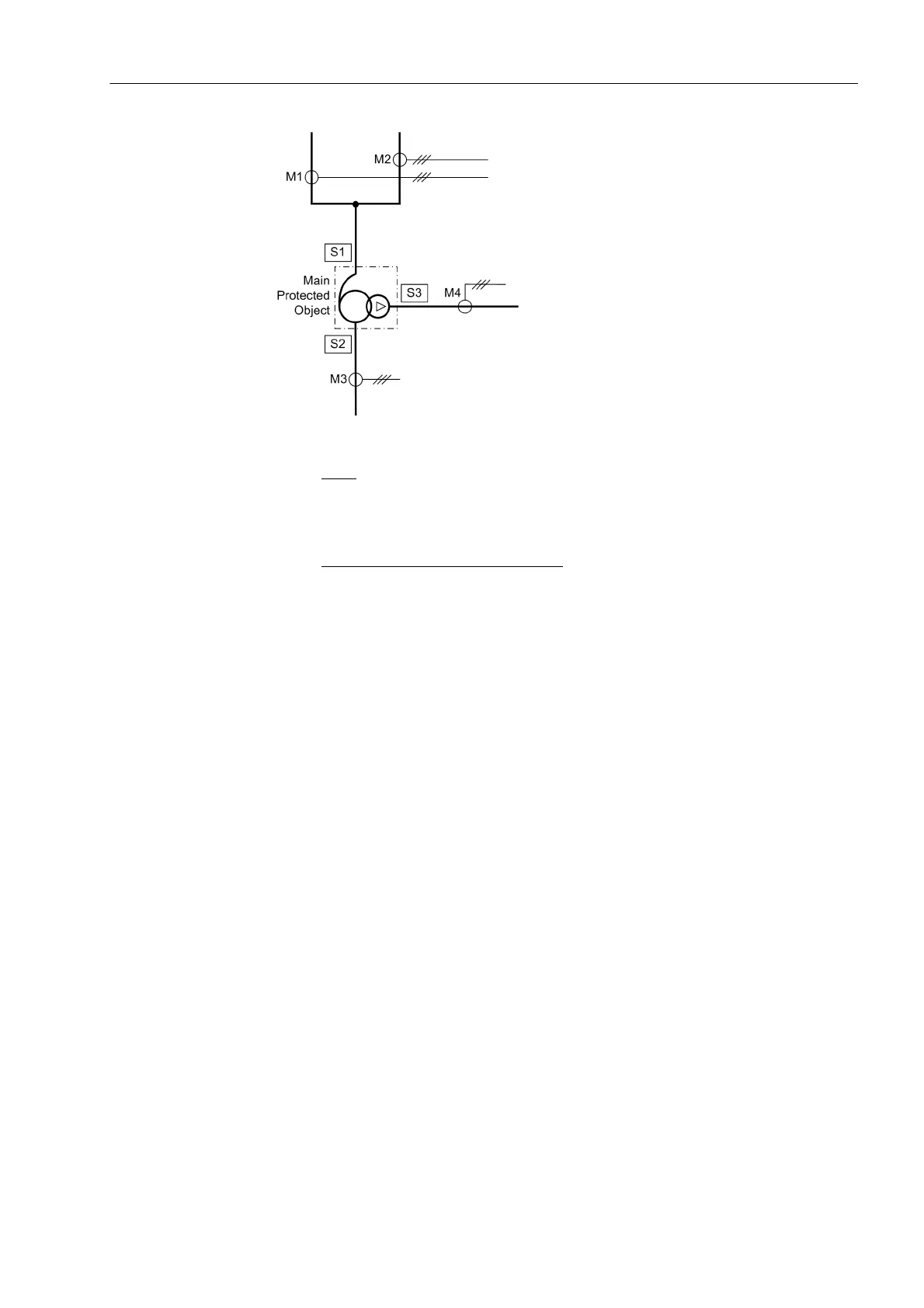
Figure 2-5 Topology of an auto-transformer with a compensation winding which is used as
tertiary winding
Sides:
S1 High voltage side of the main protected object (auto-transformer)
S2 Low voltage side of the main protected object (auto-transformer)
S3 Tertiary winding side (accessible compensation winding) of the main protected object
Measuring locations 3-phase, assigned
:
M1 Measuring location, assigned to the main protected object, side 1
M2 Measuring location, assigned to the main protected object, side 1
M3 Measuring location, assigned to the main protected object, side 2
M4 Measuring location, assigned to the main protected object, side 3
A further tap of the winding can also be used as the third side. Be aware that the num-
bering sequence always starts with the auto-connected winding: full winding, taps, and
then accessible delta winding if required.
Auto-Transformer
Banks
If three single-phase auto-transformers are arranged as a power transformer bank, the
connections of the starpoint leads of the auto-windings are accessible and often pro-
vided with current transformers. During configuration of the functional scope in section
2.1.3 you have decided whether a differential protection must be realised via the entire
transformer bank, or whether you prefer a current comparison via the winding of each
phase by means of current law.
Differential protection over the entire power transformer bank:
Regarding the first case, figure 2-6 gives an example of a 3-phase presentation. In this
example we have 3 sides and 3 assigned three-phase measuring locations. The auto-
connected winding terminals form the sides S1 (full winding) and S2 (tap) with the as-
signed 3-phase measuring locations M1 and M2. As the delta winding functions both
as the tertiary winding and the compensation winding, it is the third side S3 with mea-
suring location M3.
The currents measured in the starpoint connections are not immediately required.
However, you can assign it to a further three-phase measuring location. The device
then calculates the current sum as earth current, if this had been set accordingly in the
differential protection (see section 2.2.7).
 Loading...


