Diagnostics
5.2 Diagnostics using LEDs
Commissioning with Startdrive
144 Commissioning Manual, (IH3), 07/2016, 6SL3097-4AA10-0BP0
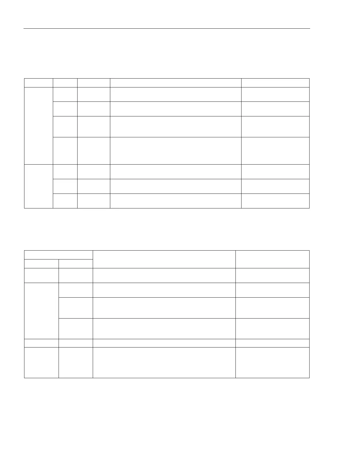
Smart Line Modules booksize 5 kW and 10 kW
Table 5- 7 Meaning of the LEDs at the Smart Line Modules 5 kW and 10 kW
READY – Off Electronic power supply is missing or outside permissi-
–
Green Continuous
Component is ready to operate. –
Yellow Continuous
light
Pre-charging not completed.
Bypass relay dropped out
EP terminals not supplied with 24 VDC.
–
Red Continuous
light
Overtemperature
Overcurrent
Diagnose fault (via output
terminals) and
acknowledge it (via input
DC LINK – Off Electronic power supply is missing or outside permissi-
–
Yellow Continuous
DC link voltage within permissible tolerance range. –
Red Continuous
DC link voltage outside permissible tolerance range.
Check the line voltage.
Smart Line Modules booksize 16 kW to 55 kW
Table 5- 8 Meaning of the LEDs at the Smart Line Modules ≥ 16 kW
Off Off Electronic power supply is missing or outside permissible
–
Green Off The component is ready for operation and cyclic DRIVE-
CLiQ communication is taking place.
–
Orange The component is ready for operation and cyclic DRIVE-
CLiQ communication is taking place.
The DC link voltage is present.
–
Red The component is ready for operation and cyclic DRIVE-
CLiQ communication is taking place.
The DC link voltage is too high.
Check the line voltage
DRIVE-CLiQ communication is being established.
Red – At least one fault is present in this component.
LED is controlled irrespective of the corresponding messag-
Remedy and acknowledge
fault
 Loading...


