Configuration
6.2 Configuring the busbar run layout
SIVACON 8PS - Configuring with LX system
Configuration Manual, 10/2011, A5E02194899-02
115
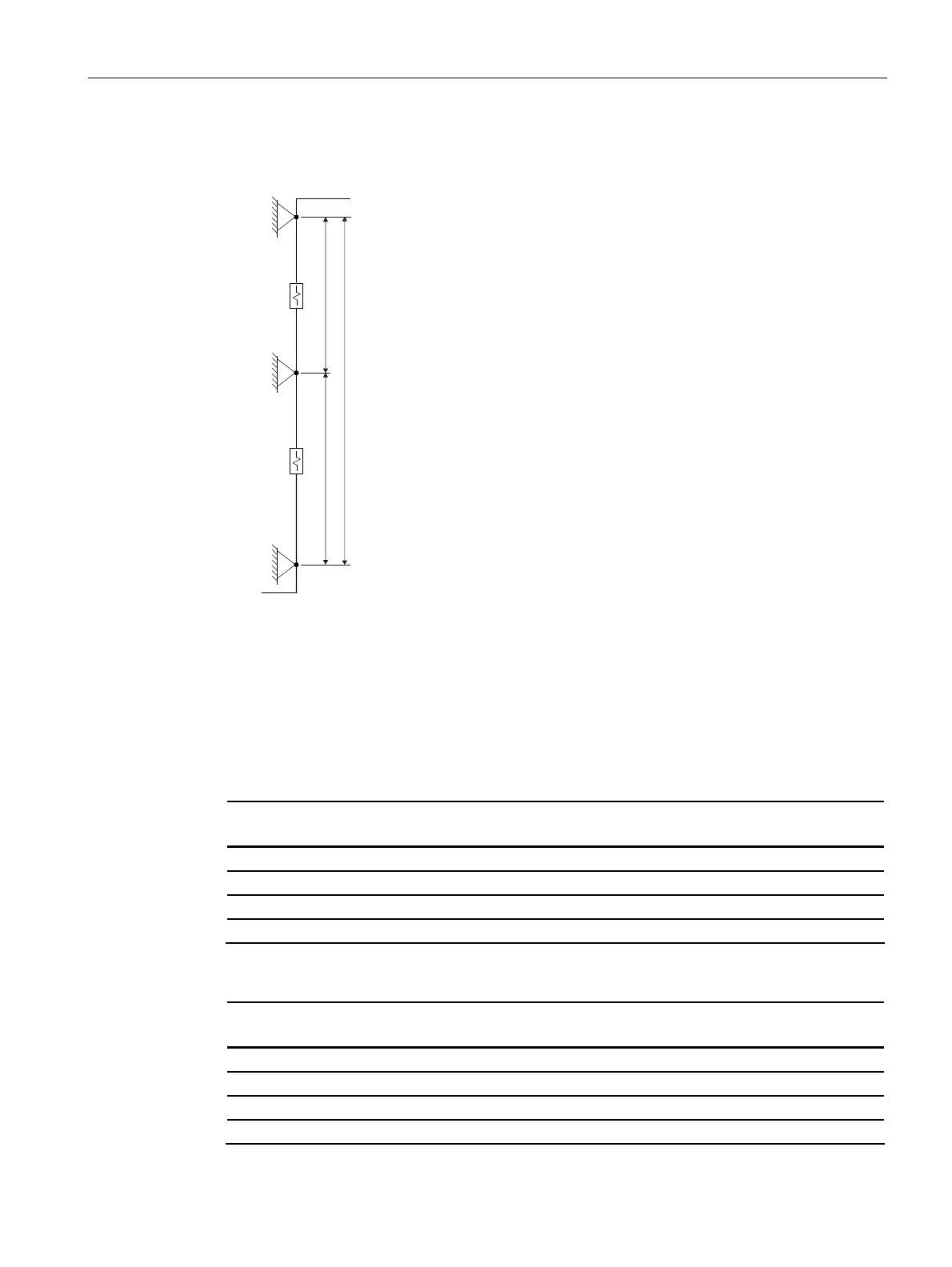
Vertical busbar run layout between two junction units, Case 1
● Always position the expansion compensation units in the centre between the fixed points.
)3
)3
'
)3
//
/
'
L1 Max. permissible sub-length
L Total run length
D Expansion compensation
FP Fixed point (type: LX-BVFP..)
EF End cap
Examples of power transmission with LXA...., (LXC....)
Run length L
[m]
Number of fixed points (FP) Number of expansion
compensation units (D)
≤ 6 (≤ 6) 2 0
≤ 25 (≤ 40) 2 1
≤ 50 (≤ 80) 3 2
≤ 75 (≤ 120) 4 3
Examples of power distribution with LXA...., (LXC....)
Run length L
[m]
Number of fixed points (FP) Number of expansion
compensation units (D)
≤ 6 (≤ 6) 2 0
≤ 50 (≤ 60) 2 1
≤ 100 (≤ 120) 3 2
≤ 150 (≤ 180) 4 4
 Loading...


