65
EN
2
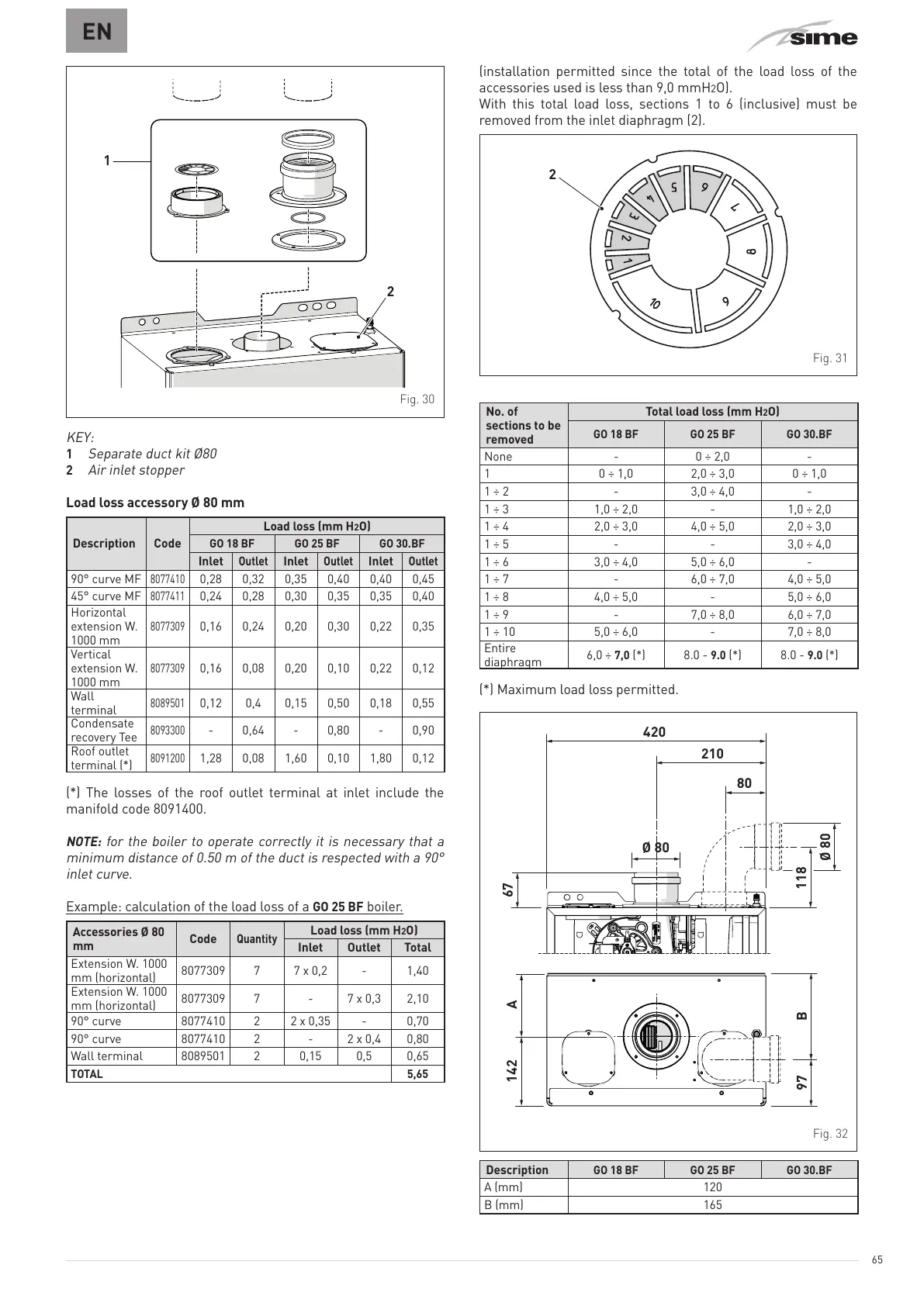
Fig. 30
KEY:
1
Separate duct kit Ø80
2
Air inlet stopper
Load loss accessory Ø 80 mm
Description Code
Load loss (mm H
2
O)
GO 18 BF GO 25 BF GO 30.BF
Inlet
Outlet
Inlet
Outlet
Inlet
Outlet
90° curve MF
8077410
0,28 0,32 0,35 0,40 0,40 0,45
45° curve MF
8077411
0,24 0,28 0,30 0,35 0,35 0,40
Horizontal
extension W.
1000 mm
8077309
0,16 0,24 0,20 0,30 0,22 0,35
Vertical
extension W.
1000 mm
8077309
0,16 0,08 0,20 0,10 0,22 0,12
Wall
terminal
8089501
0,12 0,4 0,15 0,50 0,18 0,55
Condensate
recovery Tee
8093300
- 0,64 - 0,80 - 0,90
Roof outlet
terminal (*)
8091200
1,28 0,08 1,60 0,10 1,80 0,12
(*) The losses of the roof outlet terminal at inlet include the
manifold code 8091400.
NOTE:
for the boiler to operate correctly it is necessary that a
minimum distance of 0.50 m of the duct is respected with a 90°
inlet curve.
Example: calculation of the load loss of a
GO 25 BF
boiler.
Accessories Ø 80
mm
Code
Quantity
Load loss (mm H
2
O)
Inlet Outlet Total
Extension W. 1000
mm (horizontal)
8077309 7 7 x 0,2 - 1,40
Extension W. 1000
mm (horizontal)
8077309 7 - 7 x 0,3 2,10
90° curve 8077410 2 2 x 0,35 - 0,70
90° curve 8077410 2 - 2 x 0,4 0,80
Wall terminal 8089501 2 0,15 0,5 0,65
TOTAL 5,65
(installation permitted since the total of the load loss of the
accessories used is less than 9,0 mmH
2
O).
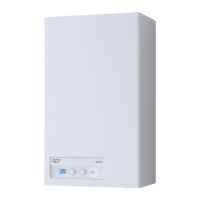
With this total load loss, sections 1 to 6 (inclusive) must be
removed from the inlet diaphragm (2).
Fig. 31
No. of
sections to be
removed
Total load loss (mm H
2
O)
GO 18 BF GO 25 BF GO 30.BF
None - 0 ÷ 2,0 -
1 0 ÷ 1,0 2,0 ÷ 3,0 0 ÷ 1,0
1 ÷ 2 - 3,0 ÷ 4,0 -
1 ÷ 3 1,0 ÷ 2,0 - 1,0 ÷ 2,0
1 ÷ 4 2,0 ÷ 3,0 4,0 ÷ 5,0 2,0 ÷ 3,0
1 ÷ 5 - - 3,0 ÷ 4,0
1 ÷ 6 3,0 ÷ 4,0 5,0 ÷ 6,0 -
1 ÷ 7 - 6,0 ÷ 7,0 4,0 ÷ 5,0
1 ÷ 8 4,0 ÷ 5,0 - 5,0 ÷ 6,0
1 ÷ 9 - 7,0 ÷ 8,0 6,0 ÷ 7,0
1 ÷ 10 5,0 ÷ 6,0 - 7,0 ÷ 8,0
Entire
diaphragm
6,0 ÷
7,0
(*) 8.0 -
9.0
(*) 8.0 -
9.0
(*)
(*) Maximum load loss permitted.
210
97 B
Ø 80
118
80
67
Ø 80
A142
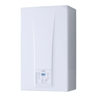
Fig. 32
Description
GO 18 BF GO 25 BF GO 30.BF
A (mm) 120
B (mm) 165