79
EN
8.3.2 Cleaning the burner
The burner does not require any particular maintenance simply
dust it with a soft brush.
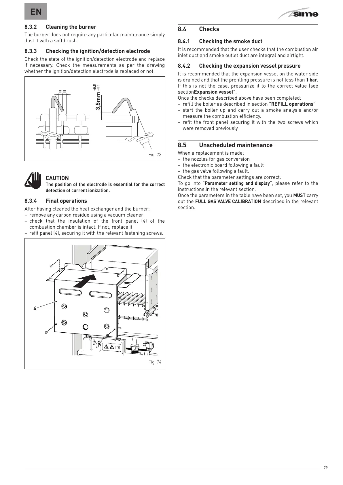
8.3.3 Checking the ignition/detection electrode
Check the state of the ignition/detection electrode and replace
if necessary. Check the measurements as per the drawing
whether the ignition/detection electrode is replaced or not.
=
=
3,5mm
-0,5
Fig. 73
m
CAUTION
The position of the electrode is essential for the correct
detection of current ionization.
8.3.4 Final operations
After having cleaned the heat exchanger and the burner:
– remove any carbon residue using a vacuum cleaner
– check that the insulation of the front panel (4) of the
combustion chamber is intact. If not, replace it
– refit panel (4), securing it with the relevant fastening screws.
4
Fig. 74
8.4 Checks
8.4.1 Checking the smoke duct
It is recommended that the user checks that the combustion air
inlet duct and smoke outlet duct are integral and airtight.
8.4.2 Checking the expansion vessel pressure
It is recommended that the expansion vessel on the water side
is drained and that the prefilling pressure is not less than
1 bar
.
If this is not the case, pressurize it to the correct value (see
sectionExpansion vessel".
Once the checks described above have been completed:
– refill the boiler as described in section "REFILL operations"
– start the boiler up and carry out a smoke analysis and/or
measure the combustion efficiency.
– refit the front panel securing it with the two screws which
were removed previously
8.5 Unscheduled maintenance
When a replacement is made:
– the nozzles for gas conversion
– the electronic board following a fault
– the gas valve following a fault.
Check that the parameter settings are correct.
To go into "
Parameter setting and display
“, please refer to the
instructions in the relevant section.
Once the parameters in the table have been set, you
MUST
carry
out the
FULL GAS VALVE CALIBRATION
described in the relevant
section.