75
EN
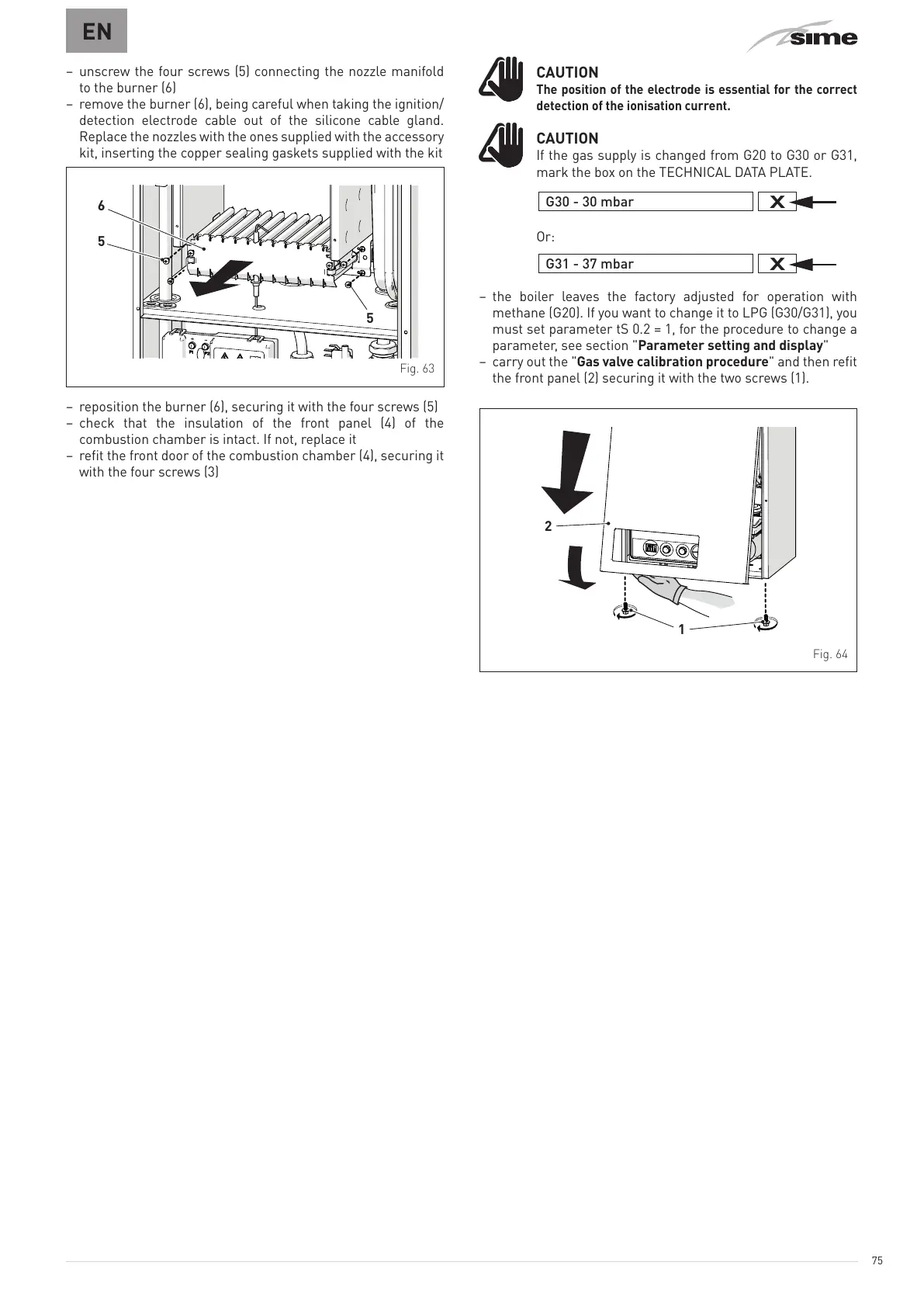
– unscrew the four screws (5) connecting the nozzle manifold
to the burner (6)
– remove the burner (6), being careful when taking the ignition/
detection electrode cable out of the silicone cable gland.
Replace the nozzles with the ones supplied with the accessory
kit, inserting the copper sealing gaskets supplied with the kit
5
6
5
Fig. 63
– reposition the burner (6), securing it with the four screws (5)
– check that the insulation of the front panel (4) of the
combustion chamber is intact. If not, replace it
– refit the front door of the combustion chamber (4), securing it
with the four screws (3)
m
CAUTION
The position of the electrode is essential for the correct
detection of the ionisation current.
m
CAUTION
If the gas supply is changed from G20 to G30 or G31,
mark the box on the TECHNICAL DATA PLATE.
G30 - 30 mbar
Or:
G31 - 37 mbar
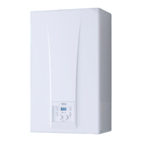
– the boiler leaves the factory adjusted for operation with
methane (G20). If you want to change it to LPG (G30/G31), you
must set parameter tS 0.2 = 1, for the procedure to change a
parameter, see section "Parameter setting and display"
– carry out the "Gas valve calibration procedure" and then refit
the front panel (2) securing it with the two screws (1).
1
2
Fig. 64