77
EN
Adjusting MINIMUM
– turn dial
t
to the minimum and leave dial
D
at the maximum
– the boiler will go to minimum operating conditions and the
display will show the message "
P00
" (indicating that it is
possible to adjust the minimum)
– press a button (
>
or
<
), the display will show a number
between 0 and 150
– press button
>
, to increase the value, or button
<
, to reduce
the value, until you see on the pressure gauge the pressure
value given in the table.
Once the required adjustment has been made, save it by
continually turning the dial
D
to the minimum value and
immediately afterwards to the maximum setpoint value.
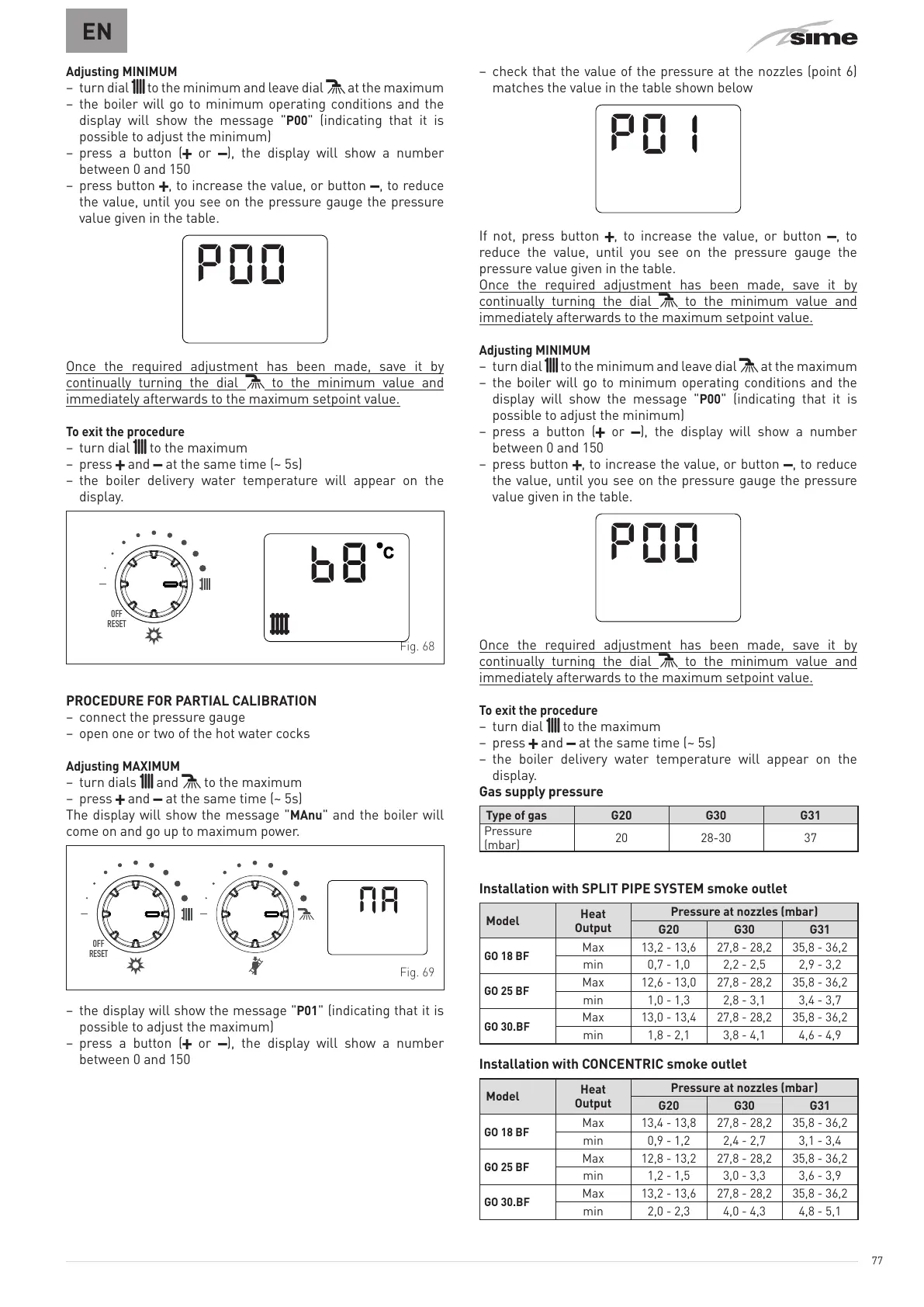
To exit the procedure
– turn dial
t
to the maximum
– press
>
and
<
at the same time (~ 5s)
– the boiler delivery water temperature will appear on the
display.
OFF
RESET
Fig. 68
PROCEDURE FOR PARTIAL CALIBRATION
– connect the pressure gauge
– open one or two of the hot water cocks
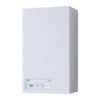
Adjusting MAXIMUM
– turn dials
t
and
D
to the maximum
– press
>
and
<
at the same time (~ 5s)
The display will show the message "
MAnu
" and the boiler will
come on and go up to maximum power.
OFF
RESET
Fig. 69
– the display will show the message "
P01
" (indicating that it is
possible to adjust the maximum)
– press a button (
>
or
<
), the display will show a number
between 0 and 150
– check that the value of the pressure at the nozzles (point 6)
matches the value in the table shown below
If not, press button
>
, to increase the value, or button
<
, to
reduce the value, until you see on the pressure gauge the
pressure value given in the table.
Once the required adjustment has been made, save it by
continually turning the dial
D
to the minimum value and
immediately afterwards to the maximum setpoint value.
Adjusting MINIMUM
– turn dial
t
to the minimum and leave dial
D
at the maximum
– the boiler will go to minimum operating conditions and the
display will show the message "
P00
" (indicating that it is
possible to adjust the minimum)
– press a button (
>
or
<
), the display will show a number
between 0 and 150
– press button
>
, to increase the value, or button
<
, to reduce
the value, until you see on the pressure gauge the pressure
value given in the table.
Once the required adjustment has been made, save it by
continually turning the dial
D
to the minimum value and
immediately afterwards to the maximum setpoint value.
To exit the procedure
– turn dial
t
to the maximum
– press
>
and
<
at the same time (~ 5s)
– the boiler delivery water temperature will appear on the
display.
Gas supply pressure
Type of gas G20 G30 G31
Pressure
(mbar)
20 28-30 37
Installation with SPLIT PIPE SYSTEM smoke outlet
Model
Heat
Output
Pressure at nozzles (mbar)
G20 G30 G31
GO 18 BF
Max 13,2 - 13,6 27,8 - 28,2 35,8 - 36,2
min 0,7 - 1,0 2,2 - 2,5 2,9 - 3,2
GO 25 BF
Max 12,6 - 13,0 27,8 - 28,2 35,8 - 36,2
min 1,0 - 1,3 2,8 - 3,1 3,4 - 3,7
GO 30.BF
Max 13,0 - 13,4 27,8 - 28,2 35,8 - 36,2
min 1,8 - 2,1 3,8 - 4,1 4,6 - 4,9
Installation with CONCENTRIC smoke outlet
Model
Heat
Output
Pressure at nozzles (mbar)
G20 G30 G31
GO 18 BF
Max 13,4 - 13,8 27,8 - 28,2 35,8 - 36,2
min 0,9 - 1,2 2,4 - 2,7 3,1 - 3,4
GO 25 BF
Max 12,8 - 13,2 27,8 - 28,2 35,8 - 36,2
min 1,2 - 1,5 3,0 - 3,3 3,6 - 3,9
GO 30.BF
Max 13,2 - 13,6 27,8 - 28,2 35,8 - 36,2
min 2,0 - 2,3 4,0 - 4,3 4,8 - 5,1