1-15
Table 1-2 assumes a door height of seven feet and a distance from the doorknob to the knob side
of the door of three inches. If your door does not meet these requirements, or has opening
hardware other than a doorknob, such as panic hardware, then refer to the ASHRAE publication
Design of Smoke Control Systems for Buildings for a formula to calculate the proper opening
force. The door widths in Table 1-2 are only valid for doors that are hinged at one end. For other
types of doors, see the ASHRAE document.
Many door closers vary the amount of force as the door opens. They provide less resistance in the
early stages of opening the door than they do later, when the door is almost fully open. The force
to open the door shown in Table 1-2 represents the force needed to open the door only enough to
let air flow through the opening. Once air is able to flow, the force exerted by the difference in air
pressure on the door lessens. Therefore, when calculating the force required to open the door, you
may need to lower the door closer force.
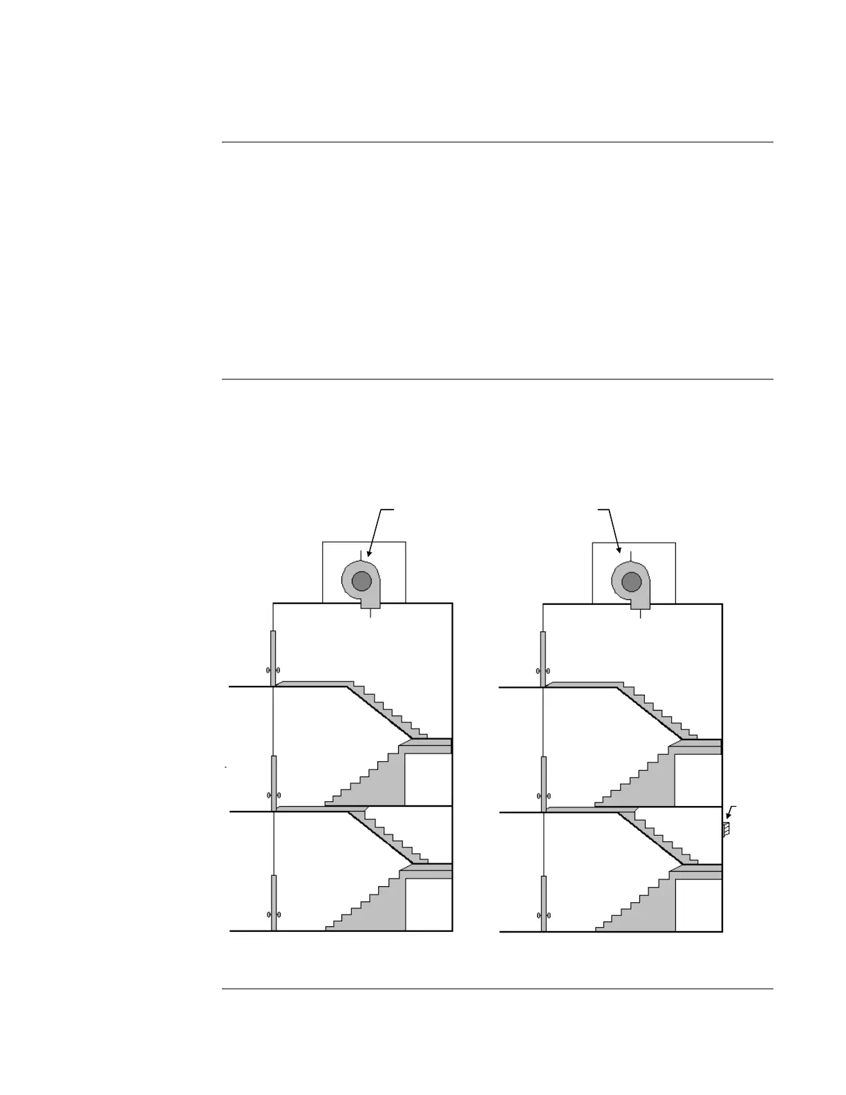
Stairtower smoke control systems are divided into two categories: “non-compensated” and
“compensated.” These categories are illustrated in the figure below, which shows stairtower
pressurization by top injection. Non-compensated systems simply turn on a fan to pressurize the
stairtower, as shown below in Stairtower A. The fan speed does not change to compensate for
doors opening and closing. The more doors that are open, the more the pressure differential
between the stairtower and the building drops.
Figure 1-6. Non-Compensated and Compensated Stairtower Systems
Continued on next page
Designing a Dedicated Smoke Control System, Continued
Ensuring Doors
Can Open
Controlling Pressure
in a Stairtower
Constant
Fan Speed
Variable
Fan Speed
Vent
Stairtower A
Stairtower B