4-6
Dedicated Smoke Control System wiring is usually straightforward. The Smoke Control System is
the only source for commands to the fans and dampers, and therefore bypass and cut-off relays are
not needed. The following sections illustrate some examples of dedicated fan and damper control.
Damper control is a basic function of the Simplex Smoke Control System. Interconnections to
motorized dampers are shown in Figures 4-2 and 4-3.
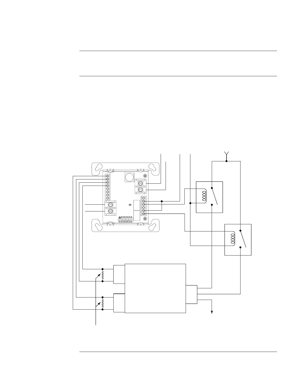
The figure below shows dedicated motorized damper control using a 4090-9120 6-Point I/O
Module. Both relay outputs are used, one to control opening the damper and the other to control
closing it.
The wiring between the 6-Point I/O Module and the control relays is unsupervised, so the module
must be mounted within three feet of the relays/dampers in accordance with NFPA 72.
Note: The wiring to the limit switches is supervised and limited to 500 ft. (152 m).
SMOKE DAMPER
DAMPER
CLOSED
POWER
RETURN
DAMPER
OPEN
POWER
N/O
MOTOR
COMM
CLOSED POSITION
LIMIT SWITCH
OPEN POSITION
LIMIT SWITCH
N/O
COMM
POWER
SOURCE
6.8 K 1/2 W EOLR
(Per Installation Instructions, 574-876)
IDNet +
IDNet -
INPUT 1
COMM
N/O
COMM
N/O
INPUT 2
LISTED
CONTROL
RELAY
(N/O)
LISTED
CONTROL
RELAY
(N/O)
+24V
FROM
FACP
1A @ 30 VDC
or
1/4 A @ 120 VAC
0V
Figure 4-2. Dedicated Motorized Damper Control Using a 6-Point I/O Module
Continued on next page
Dedicated Smoke Control System Wiring
Overview
Dedicated
Damper Control