4-11
Feedback of the closure is accomplished using a 4090-9120 6-Point I/O Module to monitor the
closed position limit switch on the damper. The module also communicates with the Simplex
FACP via IDNet. Wiring from the module to the control relay is unsupervised, so it must be
mounted within three feet of the relay/damper in accordance with NFPA 72.
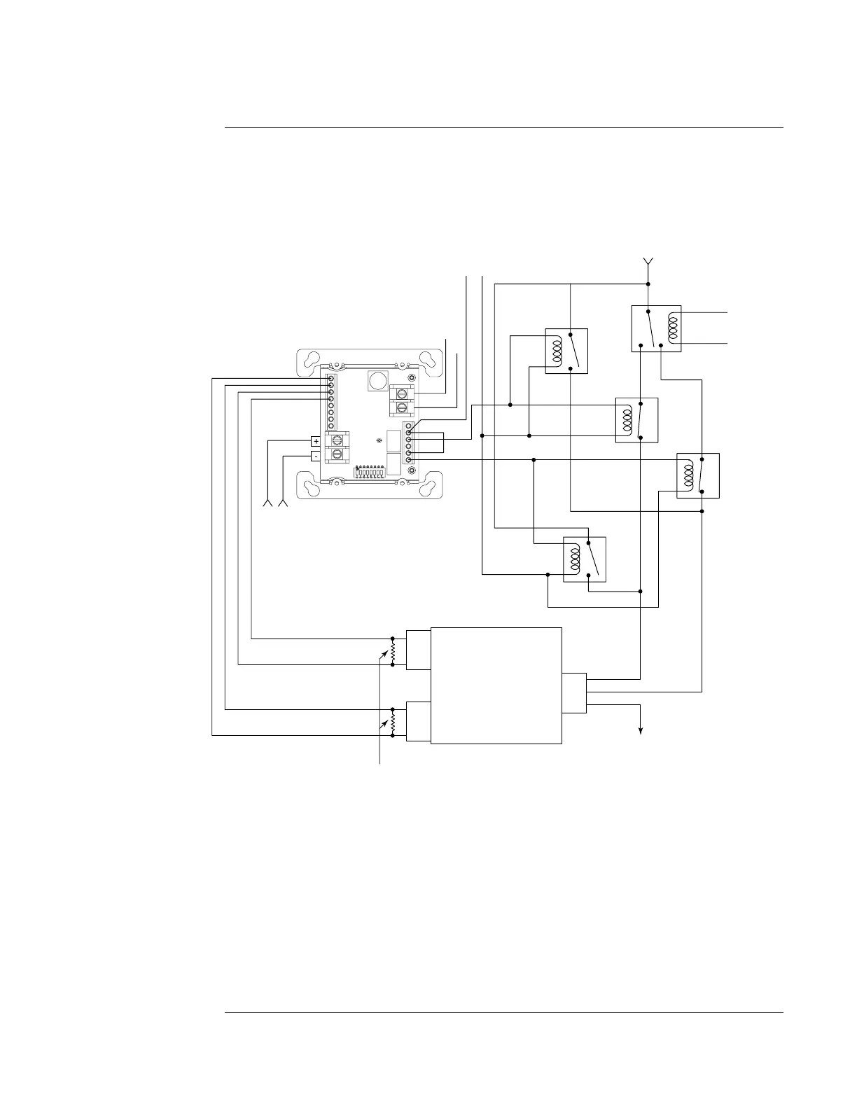
The figure below shows non-dedicated motorized damper control using the 6-Point I/O Module.
SMOKE DAMPER
LISTED
RELAY
(N/C)
LISTED
RELAY
(N/O)
(A)
(B)
LISTED
RELAY
(N/C)
DAMPER
CLOSED
POWER
RETURN
DAMPER
OPEN
POWER
N/O
MOTOR
COMM
CLOSED POSITION
LIMIT SWITCH
OPEN POSITION
COMM
COMM
N/O
N/O
INPUT 1
INPUT 2
LIMIT SWITCH
N/O
COMM
POWER
+24V
FROM
FACP
0V
SOURCE
LISTED
RELAY
(N/O)
EMS
6.8 K 1/2 W EOLR
(Per Installation Instructions, 574-876)
IDNet SLC
FROM FACP
1A @ 30 VDC
or
1/4 A @ 120 VAC
Figure 4-6. Non-Dedicated Motorized Damper Control
The two relay circuits of the 6-Point I/O Module are used, one to control opening the damper and
the other to control closing it. Relays [A] and [B] are activated to close the damper. One output
circuit controls Relay [A] to override the Energy Management System (EMS) and provide power
to the motor to close the damper. Relay [B] insures that no open power is provided to the motor
from the EMS. The other output circuit works in exactly the opposite fashion to control the
opening of the damper. The damper position is monitored by the two supervised inputs of the
6-Point I/O Module.
The wiring between the 6-Point I/O Module output circuits and the relays is unsupervised, so the
6-Point I/O Module must be mounted within three feet of the relays/dampers in accordance with
NFPA 72. The wiring to the limit switches is supervised, so no such restriction exists with the
monitor circuits.
Continued on next page
Non-Dedicated Smoke Control System Wiring Diagrams, Continued
Non-Dedicated
Damper Control