1-17
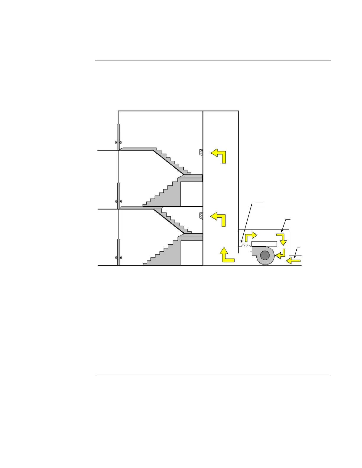
The figure below shows a bypass pressure control system for stairtower pressurization with the
bypass-around supply fan located at ground level. Although a ground-level fan is shown, the fan
can actually be placed at any level. The bypass duct dampers are controlled by one or more static
pressure sensors located between the stairtower and the building. In addition, a manually-operated
damper may be located at the top of the stairtower for smoke purging by the fire department.
Figure 1-8. A Bypass Pressure Control System
There are several ways for a compensated stairtower smoke control system to get rid of excess air
pressure to ensure that the stairtower doors can open properly. One or more vents to the building
exterior (with dampers) can be used in the stairtower to release excess pressure. These dampers
can be barometrically controlled (being forced open by the excess air pressure) or controlled by
electric motors or pneumatics as in conventional HVAC systems. In both cases, the dampers must
be placed far enough away from the air supply to prevent venting of air that has not yet been able
to disperse through the stairtower. Vents can also lead into the building, but you should consider
carefully the impact of venting extra pressure into the building before using this type of vent.
You can also use an exhaust fan to vent the excess pressure from the stairtower. Such a fan should
be designed to operate only when the stairtower is over-pressurized. It should never be on when
the pressure differential between the building and the stairtower is below the lowest limit.
Designing a Dedicated Smoke Control System, Continued
Controlling Pressure
in a Stairtower
Bypass Duct Dampers
Bypass Duct
Air Intake