5-4
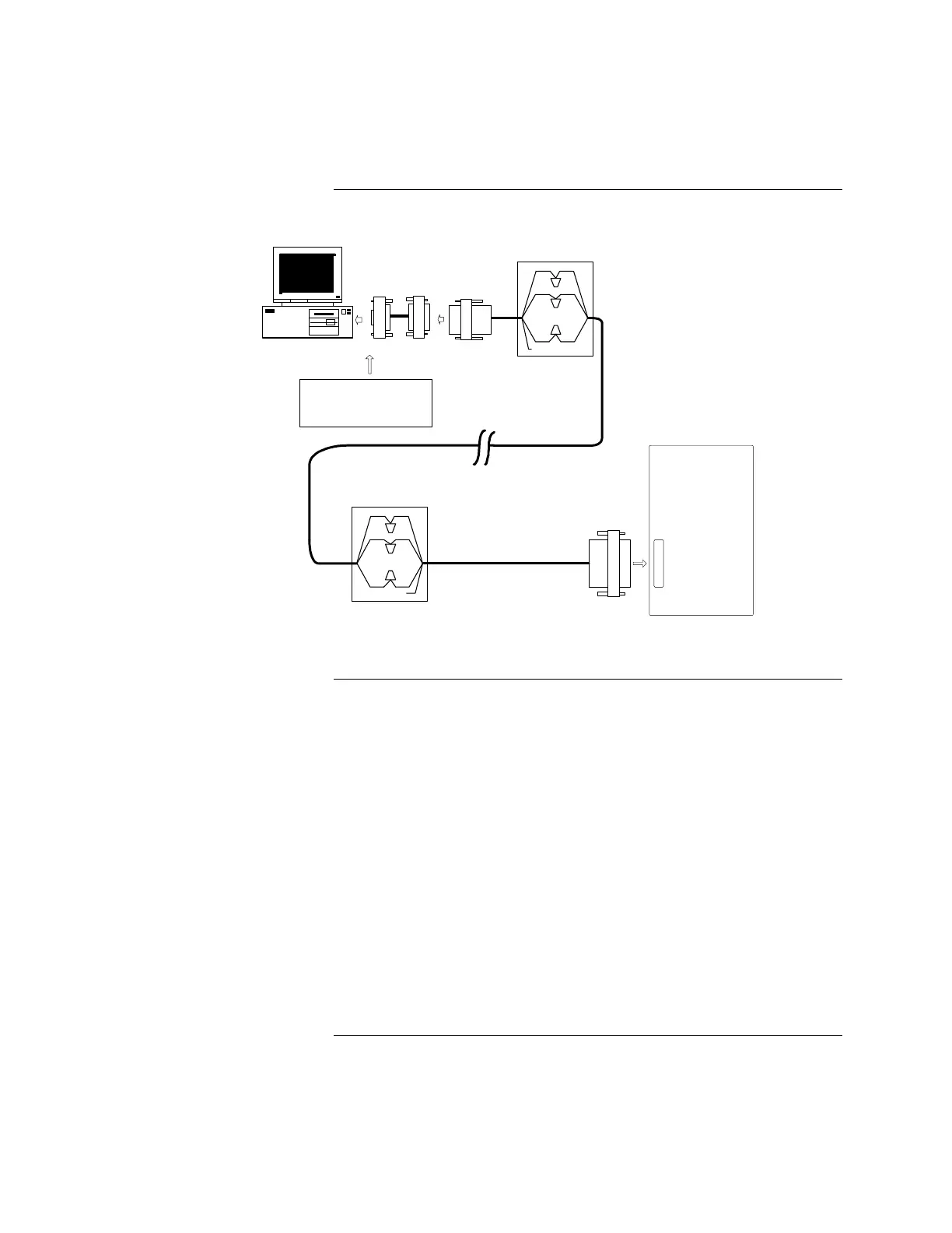
JUNCTION BOX
4190 GCC / 4120 NPU
DB25 male(pins)
6 foot
DB9 to DB25 adapter
Assy:617-836
Assy:733-571
Note: If the RS232 ports on the
GCC / NPU are DB25 male(pins),
then adapter #617-836 is not
needed.
DB25 female
Assy: 733-572
DB25 female
2120
RS-232 PORT
Rcv
RED
Xmit
n/c
NOTE : Installed Cable is typically 18AWG, 2-pair twisted.
Cable
DB9 female
Figure 5-1. Connecting 2120 Nodes to the GCC
If your RS-232 card has a DB25 male connector, complete the following steps.
Refer to Figure 5-1 for help. (If it has a DB9 male connector, complete the steps
in the previous section.)
1. Ensure that the power is OFF before starting this procedure.
2. Complete all wiring according to the wiring shown in Figure 5-1.
3. Connect the DB25 female connector of Assembly 733-571 to the RS-232
port on back of the CPU.
4. Connect the DB25 male connector of Assembly 733-572 to the RS-232 port
on the 2120 node.
5. Use the junction boxes at each end of the installed cable to terminate the
field wiring between harness 533-571 and 533-572.
6. Complete Steps 1 through 4 for each node you are installing.
7. After connecting the node(s) to the GCC, turn the power ON. The GCC
automatically boots up to the initial program screen.
Connecting the 2120 Nodes to the GCC, Continued
Installing with Adapter Cable
(Continued)
Installing without Adapter
Cable