2-5
After choosing the location for the equipment, you are ready to connect the
equipment in preparation for the installation of the software.
Note: If you need to install additional cards into the GCC, or
modify existing card settings, please do so before
connecting the equipment.
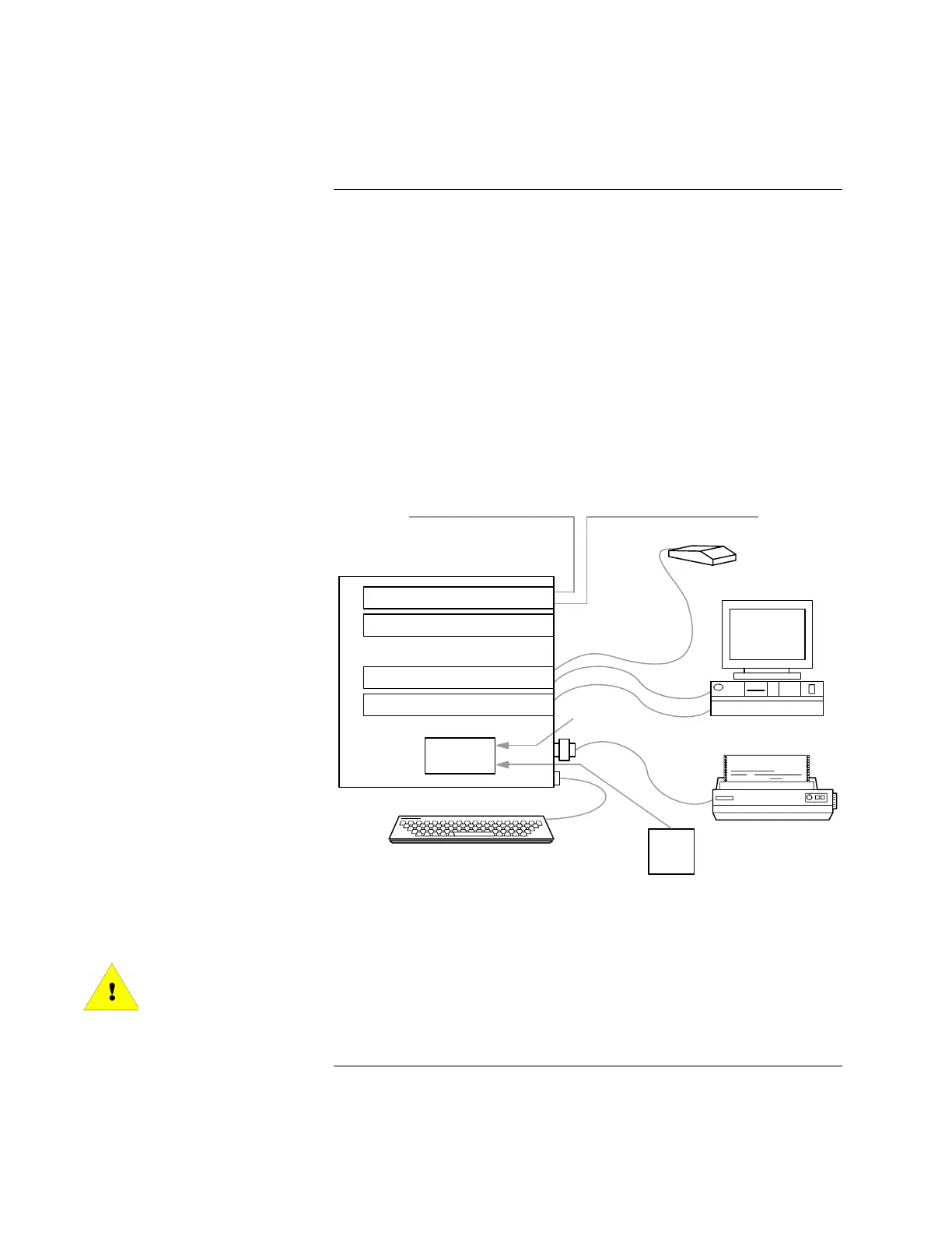
To install the hardware, place the PC in the desired location and connect the
equipment you will use with the system (printer, mouse, etc.). A typical 4190
Graphical Command Center hardware configuration is shown in Figure 2-1.
Note: Reseat the various PC boards into the motherboard. This
helps ensure that you have complete electrical connections.
The GCC rack-mount versions (17-inch and 19-inch monitors) are shown in
Chapter 4.
NETWORK INTERFACE
UL CARD
VIDEO BOARD\BUS MOUSE
TOUCH SCREEN
POWER
SUPPLY
UPS
MONITOR
PRINTER
POWER IN
4190 NETWORK COMM
4190 NETWORK COMM
Figure 2-1. Typical 4190 Graphical Command Center Block Diagram
WARNING:
Do not plug the keyboard (Part No. 636-667) or Keyboard Adapter (Part No.
636-668) into a powered NPU! This will damage the CPU board (Part No.
636-802, 636-588 or 636-995). All Equipment must be powered down before
adding any hardware.
Continued on next page
Connecting the GCC to the System
Connecting the Equipment