6-12
This section provides information about installing the cards and connecting the
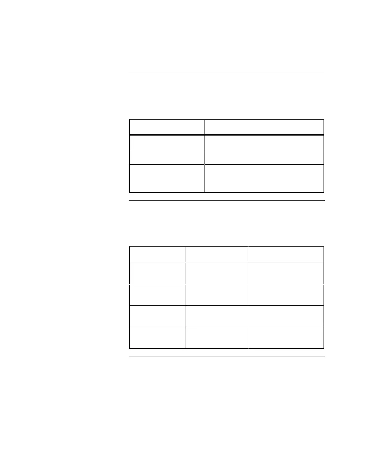
cables for the 4190-8103. Table 6-16 lists the correct slot positions in the GCC
backplane for the Network Card(s), Controller Card and UL Card.
Table 6-16. GCC 4190-8103 Model Card Slot Position
Card Slot #
Controller Card Slot #1 (Leftmost)
UL Card Slot #2
Network Card Install the first Network card in Slot #3 and
(if applicable), additional Network cards in
slots 4 through 6.
For 4190-8103 GCC systems with the terminal block mounted to the PC chassis,
verify the information listed in Table 6-17.
Table 6-17. GCC 4190-8103 Model with UL Card Device
Connection Points for Outputs 1 and 2
Location Value Function
TB1-2 to TB1-4 Short (<1 ohm) Output #1 Relay Normally
Closed
TB1-8 to TB1-10 Short (<1 ohm) Output #2 Relay Normally
Closed
TB1-4 to TB1-6 Open Circuit Output #1 Relay Normally
Open
TB1-10 to TB1-12 Open Circuit Output #2 Relay Normally
Open
Installing Cards and Jumpers, Continued
4190-8103 Card Slot
Positions
Continuity Check for GCC
4190-8103 Model with UL Card
Installed