5-2
Table 5-1 lists the required cable and connectors to complete the installation.
Figure 5-1 shows a diagram of how to connect the cables and connectors from
the RS-232 port on each 2120 node to the RS-232 connector on the CPU.
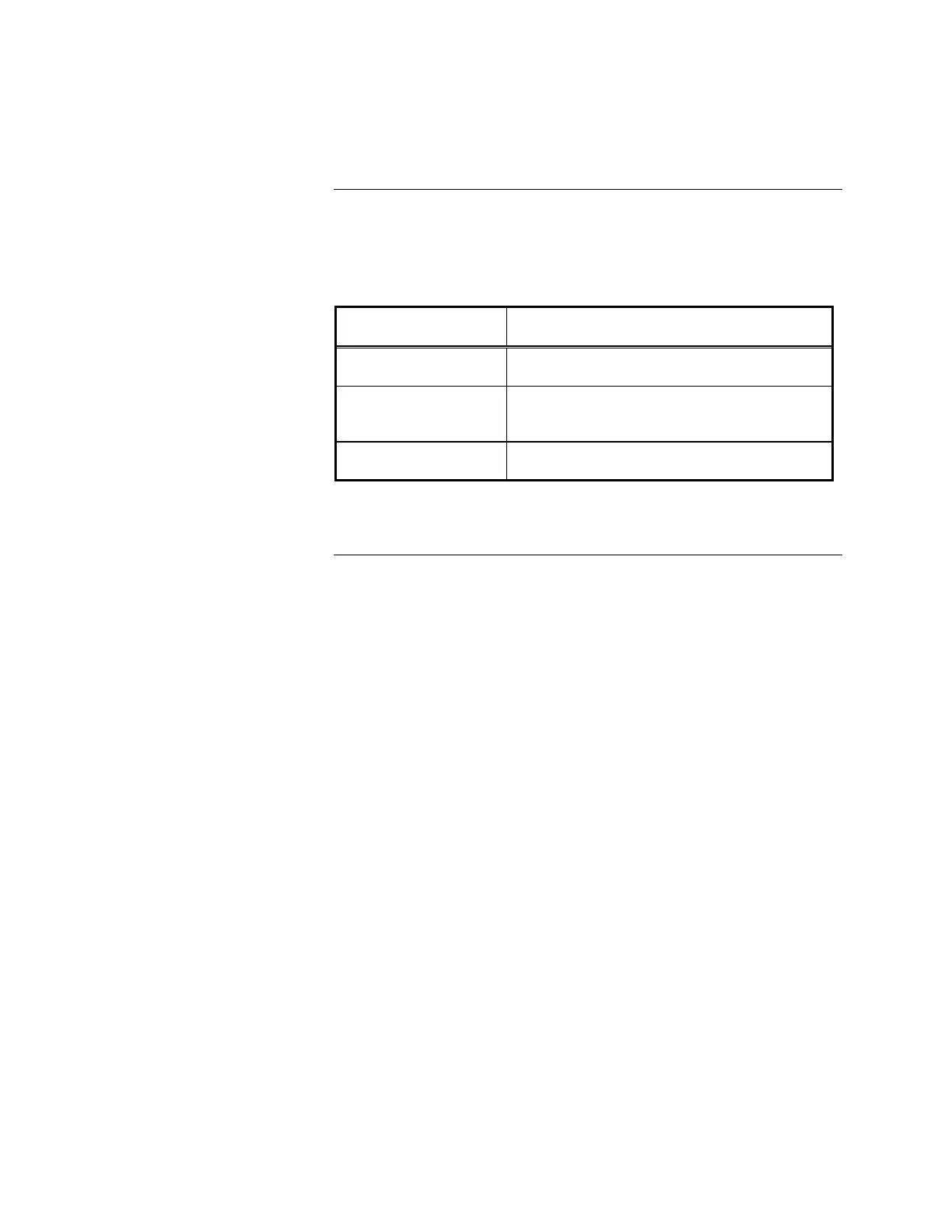
Table 5-1. Cables and Connectors for IMS Installation
Part Number Description
617-836* 6-foot (2 m) DB9 to DB25 adapter cable
733-571 Harness assembly (receptacle
suppressor)
733-572 Harness Assembly (RS-232 suppressor)
*If the RS-232 ports on the IMS are DB25 male connectors, this adapter is not
needed.
Hardware Requirements
Required Cables and
Connectors