6. INSTALLATION
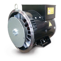
6.1 Lifting
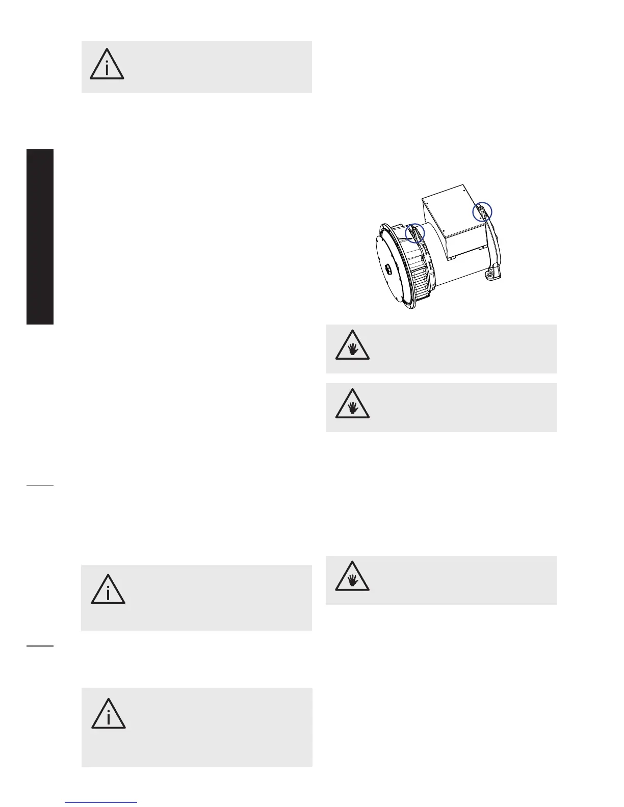
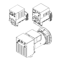
Liftandhandlethegeneratorwithsuitableequipment
eitheron a palletorby the liftinglugs locatedonthe
generatorinthepositionsindicatedinthefigure.
When lifting the HB generator use equipment with a
load bearing capacity of at least 200kg.
When lifting the IB generator use equipment with a
load bearing capacity of at least 300kg.
Whenliftingandhandlingsinglebearinggeneratorsthey
mustbekepthorizontalinordertoavoid,ifoperations
shouldgowrong,therotorfromslippingoutandbeing
damagedandpossiblycausingsevereinjury.
6.2 Mounting on engine
Fortighteningtorquesrefertosection6.2.3.
Formechanicalconnectionsitisrecommendedtouse
screwsinclass8.8.
canopyshouldbedesignedsothatthereisaminimum
clearanceof50mmbetweenthegeneratorairventand
anyflatsurface.
Thespacearoundtheairexitprotectiongridmustbe
free.
Thegenerator’srotorisdynamicallybalancedinfactory.
Theengineinducesquitecomplexvibrations,including
harmonicswithdifferentfrequencythat,whenaddedto
thegeneratorvibrations,cancausesubstantialvibration
levels dangerous for the generating set operation.
Thereforeitisessentialthattheplantengineertakesall
necessarymeasurestoensurealignmentandprovide
afirmbaseandsupportsinordertopreventvibrations
fromexceedingthestandard.
The alternator is designed to work with vibration’s
valuesasreportedinISO8528-9.
Alignment of single bearing generators is critical
becauseitmaygiverisetovibrationsalongthecoupling
betweenengineandgenerator.Forthispurposespecial
attention must be given to the alternator to engine
assembly, providing a solid base and implementing
anti-vibrationdamperstosupporttheengine/alternator
assembly.
Dual bearing generators require a rigid frame to
support theengine/generator so that a good base is
establishedforaprecisealignment.Thisframeshould
beanchoredtothebasewithanti-vibrationdampers.In
ordertominimizetwistoscillations,itisadvisabletouse
asuitablysizedflexiblejoint.
Inbelttransmissionsappliedtodualbearinggenerators
itisessentialthatthepulleydiametersandconstructions
permittheloadappliedtotheshafttobecentredwith
the length of the nub. The acceptable loads can be
requesteddirectlytotheSincro Technical Office.
Theterminalboxcontainstheinsulatedterminalsfor
connecting thephases and neutral and for the earth
connection.
The neutral is NOT connected to the housing.
Thegeneratorfaultcurrentsareavailableonrequest
to help the plant engineer in sizing the plant and its
components.
A drop in cooling air ow or inadequate
protection of the generator can lead
to damage and/or malfunction of the
windings.
WARNING!
The generator is supplied without
a connection to earth; to make this
connection refer to relevant local
regulations.Aninecientearthconnection
orsafetycut-outcancauseinjuryordeath.
WARNING!
Anerrorininstallation,use,maintenance
orreplacementofpartscancausesevere
injuryordeath,nottomentiondamageto
themachinery.Allworkonelectricaland/
or mechanical partsmust becarried out
byaqualiedspecialist.
WARNING!
An insucient loadbearing capacity can
causesevereinjuryanddamage.
CAUTION!
Theliftinglugsonthegeneratorhavebeen
designedforliftingonlythegeneratorand
notthewholegeneratingset.
CAUTION!
Beforeassembly,checkthatthecoupling
seats(bothongeneratorandengine)are
inorderandperfectlyclean.
CAUTION!
20