6.4.6 Wiring diagrams for different circuits
Intheappendixofthismanualtherearediagramsfor
connectionsotherthanthefactorystar-seriesconnec-
tion(standardunlessotherwisespeciedonorder).
6.4.7 Initial start-up
Beforestartingupthegeneratingsetcheckthatallex-
ternalconnectionsareinorderandthattheprotections
areinplace.
Duringtheinitialstart-uppayparticularattentionforany
unusualnoisethatmightsignalanincorrectalignment
betweenengineandgenerator.
Generatorsarerotatingelectricalmachinesthatinvolve
potentiallyhazardousliveormovingparts,thereforethe
followingisstrictlyprohibited:
• animproperuse;
• removalofcoversanddisconnectionofsafeties.
Dueto theseinherent hazards,all works ofelectrical
ormechanicalnaturemustbecarriedoutbyqualied
specialists.
7. AFTERSALES ASSISTANCE AND
MAINTENANCE
7.1 Control and check procedures
7.1.1 Control of windings and electrical insulation
The condition of the windings can be checked by
measuring their insulation resistance. While running
thistestdisconnectthevoltageregulatorandEMCfilter.
Itisusuallysufficienttocontrolthemainwinding.
The readings should give a measurement of at least
2 MOhm. If the insulation resistance is below this
threshold, the alternator alone should be oven dried
at 80 ÷ 100°C for 6 hours. Before carrying out this
operationremovethevoltageregulator.
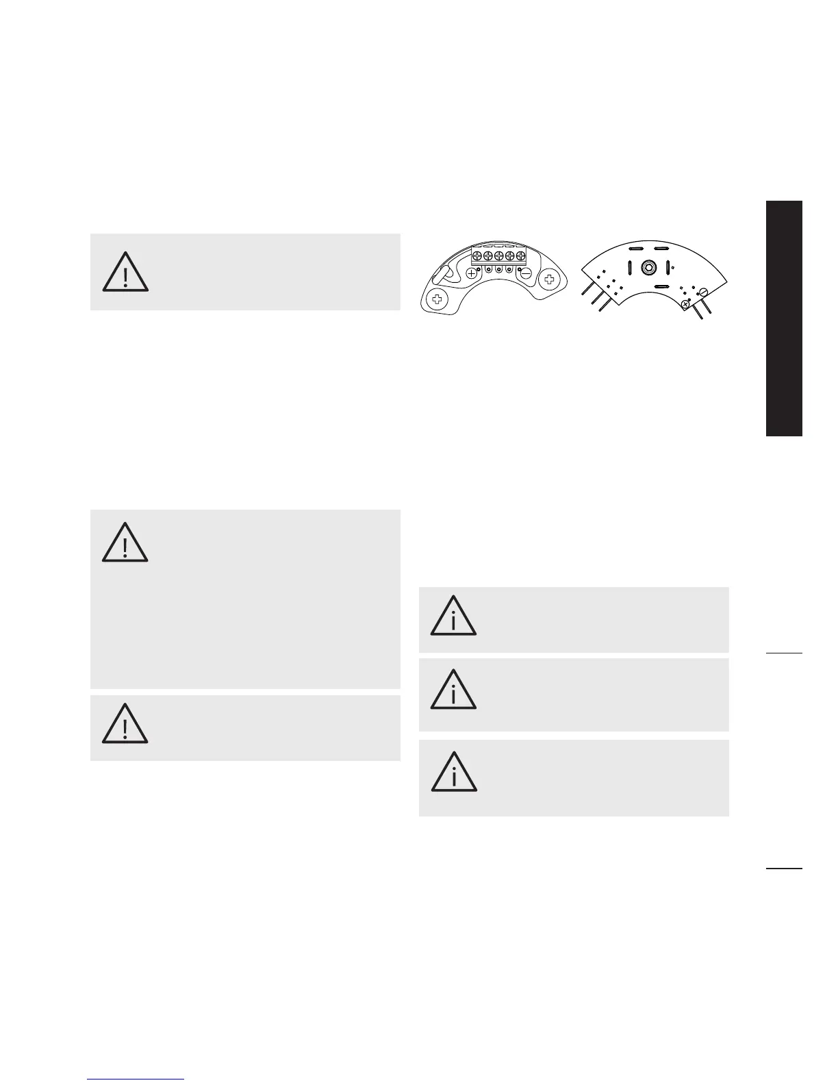
7.1.2 Control of the rotating rectifier diodes
This check can be performed with a multimeter, the
knob must be selected to the position “Diode test”.
The lead of each diode hasto beremoved fromthe
connectionswiththerotorexciter(seefigure),butit’s
not necessary to removed them from the alluminium
platewheretheyarefixed.
The faulty diode will have high (theoretically infinite)
resistance in both directions (open diode) or it can
havelowresistanceonbothdirections(diodeinshort)
by placing the tips on both directions. Meanwhile
thecorrectworking diode willhave low resistancein
forwarddirectionandhigh(theoreticallyinfinite)inthe
other(reverse)direction.
7.1.3 Control of bearings
During maintenance control the condition of the
bearings and check that no grease has leaked; the
lifespan of the bearings depends on the vibrations,
axial strains they undergo (vibrations can increase
considerablywithabadalignment)andontheworking
conditions.Socheckforanyunusualsigns:vibrations,
unusualnoises,cloggedairvents.
If undue vibrations or noises appear after long-term
usage, these could bedue to a worn bearingthat, if
damaged,hastobereplaced
The bearing should always be replaced after 20.000
working hours.
The lack of routine check-ups and poor
maintenance can causesevere damage
topersonsand/orobjects.
WARNING!
The maintenance and fault diagnostic
procedures involve risks that may
cause severe injury or even death.
These procedures should therefore be
carried out solely by qualied electrical
and mechanical specialists. Before any
maintenance and cleaning work make
surethattherearenoliveparts,thatthe
generatorhousinghascooledtoambient
temperature, that the generating set
cannotbeaccidentallystartedupandthat
allproceduresarestrictlyobserved.
WARNING!
Do not touch the generator while in
operation and immediatly after the
generatingsethasstopped,sincecertain
partsmaystillbeveryhot.
WARNING!
Long periods of sustained vibrations
can damage thebearing ballsand their
seat.Toohighhumiditycanemulsifythe
greaseandencouragecorrosion.
IMPORTANT!
Intense vibrations caused by the engine
bad alignment of the components inthe
generating set put the bearing under
stressesthatwillreduceitslifespan.
IMPORTANT!
Abearingslifespaniscloselylinkedtothe
workingconditionsandenvironment.
IMPORTANT!
IB
HB