6.4.5 RD2 AVR
TheAVR controls the generator voltage. TheAVR is
used to keep a constant voltage when the load and
machineparametersvary.
TheAVR requires a so-called sensing connection; a
powersupplyfromaspecificcircuit(AUX);anoutputto
therotor(+/-).
In case of unbalanced or distorted load, voltage
regulationaccuracycouldbereduced.
Afrequencycontrolprogressivelyreducesthegenerator
excitationwhenthedriveenginespeeddropsbelowa
pre-set,adjustablethresholdpreventingover-excitation
atlowoperatingspeedsandabatingtheloadengage
effectsontheengine.
In conclusion the regulator reaction time can be
modulatedtoeliminateanyvoltageinstabilitythatmay
arise.
The output voltage can be changed by adjusting
potentiometer“V”.Runthegeneratingsettoitsnominal
speedandturnuntil the required voltage is obtained.
If a small variation in speed causes a change in
voltage,thentheunderspeedprotectionshouldfirstbe
calibrated.
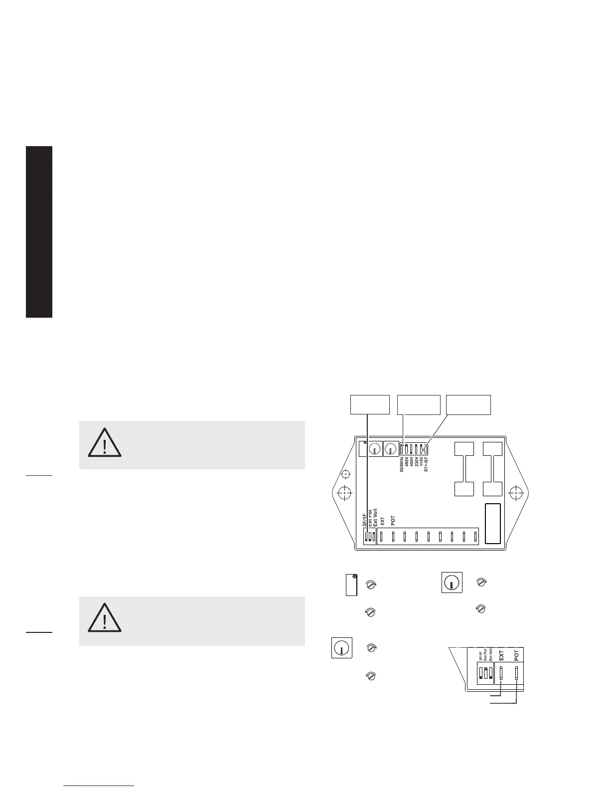
Thevoltagesensingjumpershouldbeconnected:
• toterminals“115”ifconnectedtoavoltagebetween
100 and 130V
• toterminals“230”ifconnectedtoavoltagebetween
185 and 245V.
• toterminals“400”ifconnectedtoavoltagebetween
340 and 460V.
• toterminals“480”ifconnectedtoavoltagebetween
440 and 520V.
Stability adjustment: if onload voltage fluctuations
are experienced adjust potentiometer “ST”, which
modulatesthereactiontimeoftheregulatortoexternal
inputs, thereby eliminating any instability in the
alternator-loadsystem.
IftheadjustmentviapotentiometerSTdoesnotprove
tobesufficient,ispossiblealsoto use the dip-switch
ST+/ST:movingittotheONposition(ST+)stability
increases.
Setting of the under speed protection at 50 (60)
Hz:startuprotationofthegeneratingsetadjustingitto
obtainafrequencyof46(56)Hz.Turntrimmer“UF”until
thevoltagebeginstodrop.Restorenominalspeed.
Remote voltages adjustment :wirethepotentiometer
(5kOhm, 3W)totheshortedterminals“EXT POT”.Run
thegeneratingsettoitsnominalspeedandadjustthe
externalpotentiometerandeventuallyalsothetrimmer
“V”toobtaintherequiredvoltage.
Remote voltages adjustment :
1) with potentiometer: TurnONthedip-switchEXT-
POT (and make sure the dip switches EXT-VOLT is
turnedOFF).
Wirethepotentiometer(5kOhm, 3W)totheterminals
“EXT POT”.Runthegeneratingsettoitsnominalspeed
andadjusttheexternalpotentiometerandtrimmer“V”to
obtainthedesiredvoltage.Theexternalpotentiometer
hastheeffectofincreasingthevoltagevaluesetbythe
“V”trimmer.
2) Connection with controller or cosf regulator: Turn
ONthedip-switchEXT-VOLT(andmakesurethedip
switchesEXT-POTisturnedOFF).TheAVRregulator
accepts voltage analogic input (0-10VDC, observe
polarityshowninfigure)forremotevoltageadjustment.
Tosetthesystem,followthisprocedure:
- Decrease the voltage by turning the “V” trimmer
counter-clockwise;
-Applyhalfthecontrolvoltageatthe“EXTpot”terminals
(5VDC);
- Act on the “V” trimmer to bring the voltage to the
nominalvalue;
in this way, the external controller can increase or
decreasetheoutputvoltage.
Incasetheremotevoltageadjustmentisnotused,turn
OFF the dip-switches EXT-POT and EXT-VOLT. Pay
attentionnottoturnONboththedip-switches.
If the voltage is set any higher than its
maximum limit the generator may be
damaged.
WARNING!
If the under speed is set at too low
a frequency, the generator may be
damaged.Ontheotherhand,toohigha
frequency can cause voltage drops with
highloads.
WARNING!
Frequency
Dip-switch
Voltage
Dip-switch
Phase
Dip-switch
Voltage
increasing
Voltage
decreasing
Underfrequency
protection limit
increasing
Underfrequency
protection limit
decreasing
Stability
decreasing
Stability
increasing
Connection with controller,
Observe polarity:
 Loading...