- 17 -
16642
Version 02
EN
3. General description
EN
3. General description
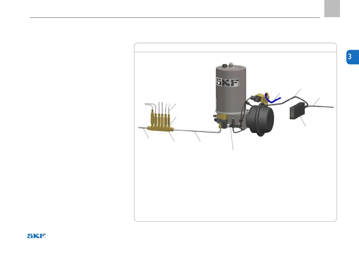
Figure 1
System operation
1. Control centre, e.g. ST-102 or ST-102P
2. 24 V DC power cable
3. Control cable
4. Pressurised air supply hose
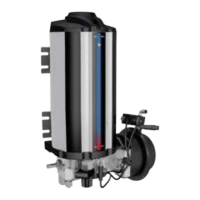
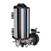
5. Pump unit 40PGA
6. Header tube or hose
7. Mounting rail
8. B doser
9. Lubrication tube or hose
3.3 System operation
The system’s operation is controlled by a
control centre, such as the ST-102 (1),
which activates the pump at predetermined
intervals. At the start of a lubrication cycle,
a control impulse from the control centre
opens a solenoid valve, allowing pressurised
air to flow into the pump (5), increasing
the pressure in the piping. When the pres-
sure in the header piping (6) increases,
pressure-forced piston dosers (8) inject a
predetermined dose of lubricant through the
lubrication tube or hose (9) to the lubrication
point. At the end of the pressurisation stage,
the control centre reverts the pump to its
rest position, and both the pump and the
doser are filled with lubricant for the next
stroke. The control centre receives power
through a 24 V DC power supply cable (2).
There is also a control cable (3) between the
control centre and the pump.
System operation
2
9
4
3
8
6
7 6
1
5
 Loading...