- 18 -
16642
Version 02
4. Design
EN
4. Design
EN
4. Design
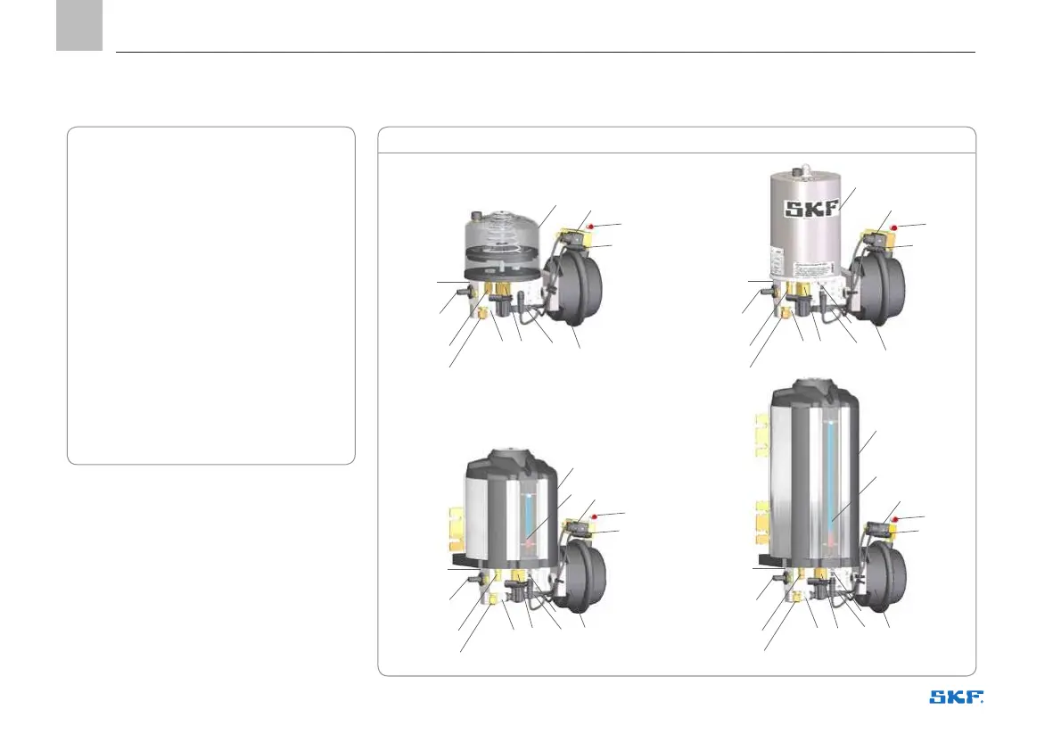
Figure 2
Main pumping unit components (Figure 2):
1. Body
2. Lubricant reservoir
The body assembly includes:
3. Low level switch
4. Solenoid valve
5. Pneumatic actuator
6. M12 branch cable
7. Filling connector
8. Filling filter
9. Pressure switch
10. Discharge valve
11. Overfill relief valve
12. Lubricant outlet
13. Visual level indicator – 4 l reservoir
14. Visual level indicator – 10 l reservoir
15. Pneumatic inlet connector
16. M12 electrical connection
9
9 7,8
7,8
7,8
7,8
3 3
3
6
6
66
5
55
5
9
9
2
2
4 4
4
4
1
10 10
1010
11 11
1111
1
1
1
2
2
14
13
12
12
12
12
15
15
15
15
16
16
16
16