- 33 -
16642
Version 02
EN
10. Functional component testing
EN
10. Functional component testing
10. Functional component testing
10.1 Control centre ST102 (P)
Connect the wire harness to the control
centre. Connect the device to a power supply
according to the wiring diagram (page 58).
When power is on, one of the LED indicators
(1 or P) in the control centre's control panel
should always be lit or flashing. If none of the
control centre lights are lit, check the vehi-
cle's power outlet fuse. The control centre’s
own fuse is of the self-resetting type, and
will reconnect power once it has cooled off.
The green LED indicator on the control cen-
tre’s circuit board indicates that the control
centre is receiving power.
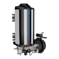
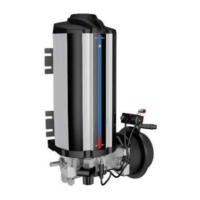
10.2 Pumping unit 40PGA
Remove the plug or connector closest to the
pump from the header tube and press the
extra lubrication button. The pump should
complete a working stroke and inject a lubri-
cant dose corresponding to its displacement
(40 cm³) through the opened connection.
10.3 Solenoid valve 40PGA
Check that the control centre receives pow-
er. Press the “Extra lubrication” button and
check whether pressurised air is discharged
at the end of the predetermined pressuri-
sation cycle through the solenoid valve’s
discharge opening. If pressure is not dis-
charged, the solenoid valve is defective.
The system can also be used manually by
turning the valve’s manual activation screw
with a screwdriver half a turn clockwise
and, after pressurisation, back to its original
position.
10.4 Alarm system – pressure switch
The pressure alarm switch monitors pres-
sure changes in the header piping. If the
pressure does not increase and decrease,
the control centre generates an alarm.
Remove the plug next to the discharge valve
(Figure 2 item 10). Press the Extra lubri-
cation button. Wait until the pressurisation
time is complete. The indicator for line 1
should start flashing.
Close the opened plug, press the extra lubri-
cation button and check that the indicator for
line 1 stops flashing.
10.5
Alarm system – reservoir low level switch
Press the Extra lubrication button and check
that the P indicator and the low level switch
indicator remain unlit.
CAUTION
Before carrying out any repair work,
take the following safety measures:
○ Prevent unauthorised access.
○ Mark and secure work area.
○ Depressurise the product.
○ Disconnect the product from
the power supply and secure it
against being switched on.
○ Ensure the device is receiving no
power.
10.6 Repairs