- 19 -
16642
Version 02
4. Design
EN
4. Design
EN
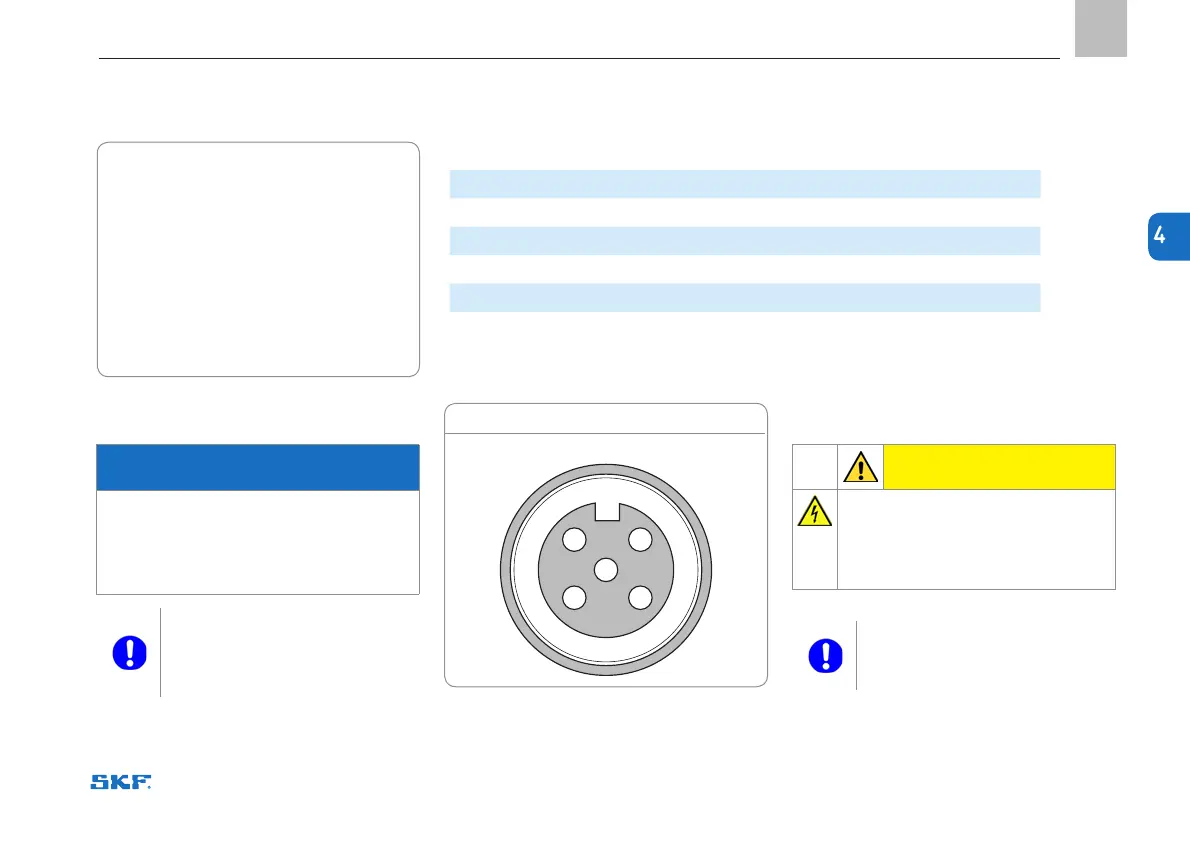
Figure 3
Table 1. M12 connection
M12 pin Cable wire colours Description
1
Brown
Low limit 24 V DC
2
White
Valve control 24 V DC
3
Blue
Pressure switch 24 V DC
4
Black
Protective Earth and Neutral 0 V DC
5 Not connected
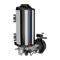
4.1 Connections
Outputs
• Lubricant outlet, Ø 8 mm
(Figure 2, item 12), thread: G 1/4"
Inputs
• Pressurised air inlet connector (Figure 2, item
15), 1 pc,
Ø 8 mm
nylon tube, barbed insert fitting
Electrical connections
• Electrical connection, M12 (Figure 2, item 16)
4.2 Pneumatic connection
NOTICE
Compressed air
Do not exceed the maximum admissible air
pressure and air volume. Before making
the connection, ensure that the air valve of
the filter regulator lubricator is closed.
Connect the compressed air
in such way that no forces are
transferred to the product (ten-
sion-free connection).
4.3 Electrical connections
CAUTION
Please remember to unplug the
products before any work on electri-
cal components.
When making connections, make
sure there is no tension on the
wires.
M12 connection
2
3
1
4
5