MAINTENANCE PROCEDURES
Engine Stopper
(600 HO E-TEC)
Engine Stopper Adjustment
The engine stopper is located on the
LH front engine support, in front of the
drive pulley.
1. Remove tether cord cap from en-
gine cut-off switch.
2. Remove the LH lower side panel, re-
fer to
CONTROLS, INSTRUMENTS
AND EQUIPMENT
.
3. Remove drive belt guard, refer to
DRIVE BELT GUARD REMOVAL
in
this su bsection.
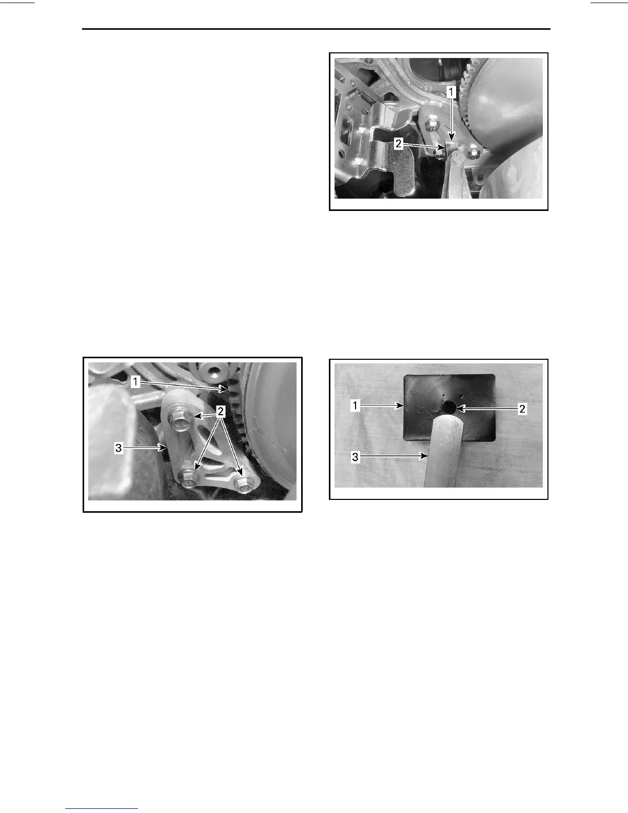
4. Loosen the three screws retaining
the engine stopper to the engine
support just enough to allow a verti-
cal play (1/2 to one turn).
mmo2010-009-007_a
1. Drive pulley
2. Engine stopper screws
3. Engine stopper
5. Insert a 0.5 mm (.02 in) feeler gauge
in the engine stopper opening (see
illustration).
mmo2010-009-001_a
1. Opening
2. Feeler gauge
6. Place feeler gauge between engine
stopper and rubber stop block (on
engine).
NOTE: Do not insert the feeler gauge
too deep, as it will pass over the bu mp
at the surface of the rubber stop block
and alter adjustment. See illustra tion.
mmo2010-009-002_a
1. Rubber stop block
2. Bump
3. Feeler gauge
7. Tighten screws to the specified
torque, following the illustra ted se-
quence. Take care not to pinch the
feeler gauge.
_______________
97




 To Next Page