Page 188 December 2007
Telescopic Boom Series
Models SJ61T & SJ66T
194312
Section 5 - ProceduresService and Maintenance
5.3-7 Electronic Tilt Switch Setup
Procedure
The following information is supplied for replacement or
reprogramming of the electronic tilt switch. Also included
are test and verication instructions. Follow the appropri-
ate procedures below.
Tilt Switch Replacement
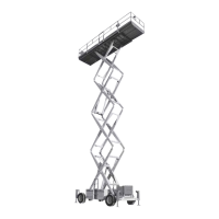
Y AXIS
X AXIS
1. Ensure aerial platform is parked on a rm level
surface.
2. Fully lower platform and retract y boom.
3. Chock or block wheels to keep the aerial platform
from rolling forward or backward.
4. Push in “ ” emergency stop buttons and turn
main disconnect switch to “ ” off position.
5. Disconnect tilt switch from 4 pin connector.
NOTE
Ensure part number of old and new tilt
switch are the same.
6. Remove old tilt switch from mount.
7. Install new switch to mount and connect switch
plug to 4 pin connector.
NOTE
The tilt circuit is only powered when controls
are powered up.
8. Turn main disconnect switch to “ ” ON position.
9. Turn base/off/platform key switch to “ ” base
position.
10. Pull out “ ” all emergency stop buttons.
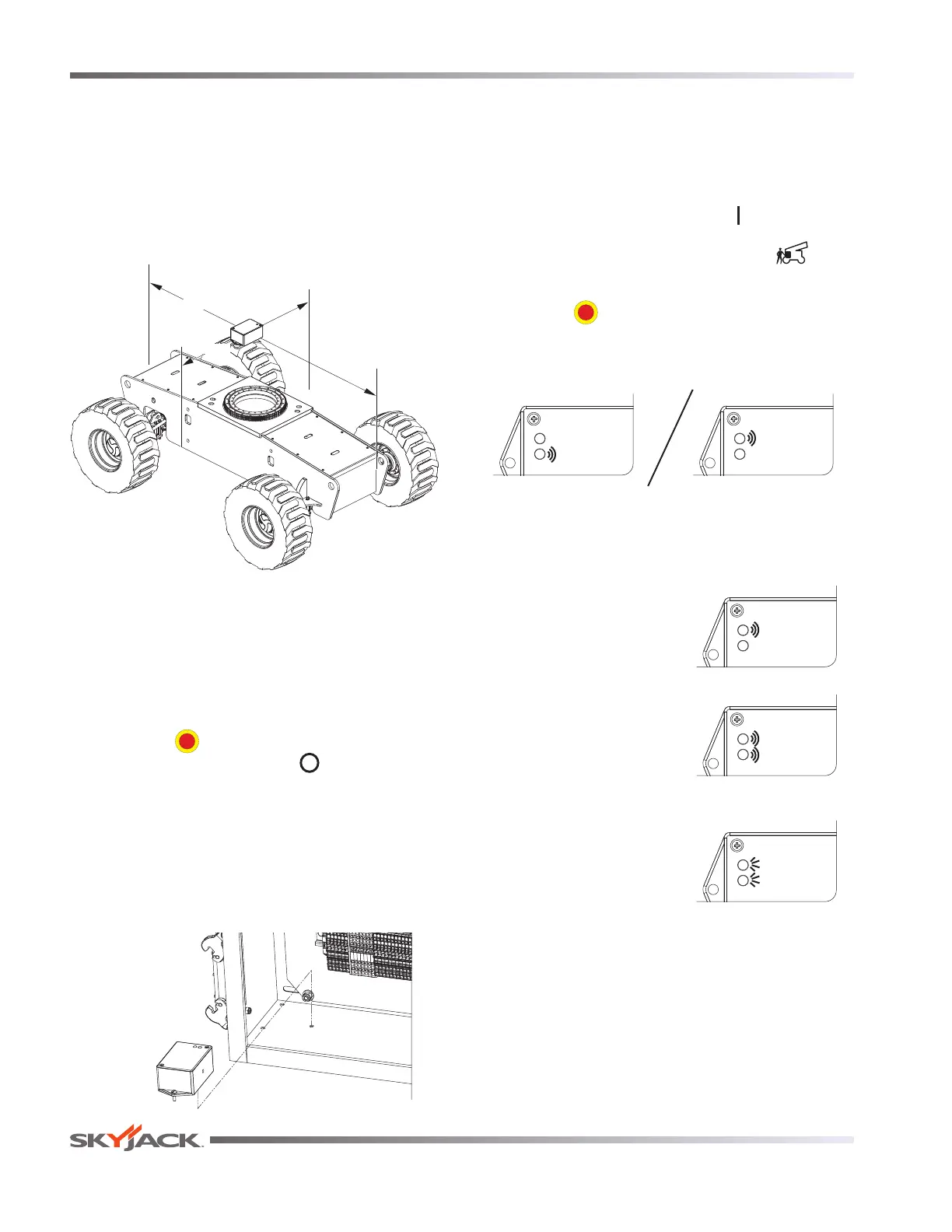
11. Verify switch is powered. (Red or green LED will be
continually blinking)
Red LED
Green LED
Red LED
Green LED
12. Program the Tilt Switch
a. Press and release the set up button 3 times.
Observe LED ash codes as shown below.
Red LED
Green LED
b. Only the red LED will
blink for 4 seconds.
Red LED
Green LED
c. Both LEDs will
flash for 1 second.
Results: The switch is
learning the new zero
position.
Red LED
Green LED
d. Both LEDs will turn
on solid for 1 second.
Results: The new zero
position has been
learned.