165
Turret Section 5 – Procedures
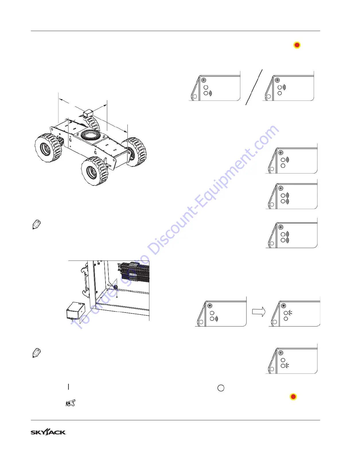
5.5-7 Electronic Tilt Switch Setup
Procedure
Tilt Switch Replacement
Y AXIS
X AXIS
1. Disconnect the tilt switch from the 4 pin
connector.
NOTE
Make sure the part number of the old tilt switch
and the new tilt switch are the same.
2. Remove the old tilt switch from the mount.
3. Install the new switch on the mount and connect
the switch plug to the 4 pin connector.
NOTE
The tilt circuit is only powered when the controls
are powered up.
4. Turn the main disconnect switch to the ON
position .
5. Turn the base/off/platform key switch to the base
position .
6. Pull out both emergency stop buttons .
7. Verify the switch is powered (red or green LED
will be continually blinking).
Red LED
Green LED
Red LED
Green LED
8. Program the tilt switch:
a. Press and release the set to zero button
3 times. Observe the LED ash codes as
shown below.
b. Only the red LED will
blink for 4 seconds.
Red LED
Green LED
c. Both LEDs will ash for
1 second.
Results: The switch is
learning the new zero
position.
Red LED
Green LED
d. Both LEDs will turn on
solid for 1 second.
Results: The new zero
position has been
learned.
Red LED
Green LED
e. The green LED will ash and then the
red LED will turn on solid for 2 seconds.
Results: The switch is verifying the new zero
position.
Red LED
Green LED
Red LED
Green LED
f. Only the red LED will
blink for 4 seconds.
Red LED
Green LED
9. Turn the main power disconnect switch to the off
position .
10. Push in the emergency stop buttons .
11. Proceed to Verify the Tilt Circuit.
To order go to Discount-Equipment.com
 Loading...