200
Section 5 – Procedures Manifolds and Hydraulic Pumps
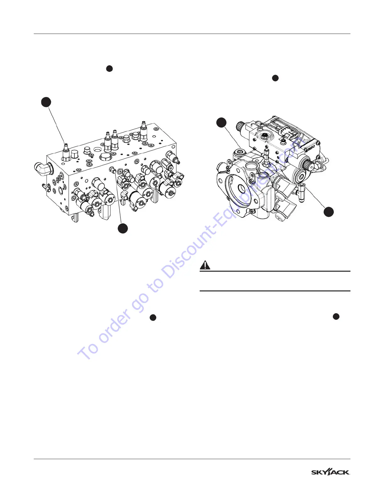
5.8-9 Fly Boom Relief Valve Adjustment
1. Locate the GP1 port
1
on the main manifold
and remove the cap.
1
7
2. Connect a pressure gauge (345 bar / 5000 psi)
to the GP1 port.
3. Start the engine from the base control console
and let it run for 2-5 minutes.
4. Fully extend the boom and check the reading
on the gauge. The pressure should be 138 bar
(2000 psi). Follow the next steps for adjusting
the pressure, if needed.
5. Locate the fly boom relief valve RV6
7
.
6. Loosen the lock nut on the fly boom relief valve
RV4. Turn the adjusting stem clockwise to
increase the pressure and counterclockwise to
decrease the pressure.
7. Tighten the lock nut on the fly boom relief valve
RV4 once 138 bar (2000 psi) is observed on
the gauge. You must fully extend the boom to
activate a pressure reading on the gauge.
5.8-10 Test Charge Pump Pressure on
Drive Pump
1. Locate test port TP3
5
on the drive pump.
2. Connect a pressure gauge (41 bar / 600 psi) to
the test port.
6
5
3. Start the engine from the base control console.
WARNING
To protect the gauge, do not activate any controls
during this procedure.
4. Check the reading on the gauge. The standard
pressure should be 22 ±2 bar (313 ±31 psi).
5. Replace the charge pump relief valve RV7
6
if
the standard pressure is not achieved.
6. Repeat steps 2, 3, and 4 after the charge pump
relief valve is replaced.
7. If the pressure is still not in range, repair or
replace the pump as necessary.
To order go to Discount-Equipment.com
 Loading...