167
Turret Section 5 – Procedures
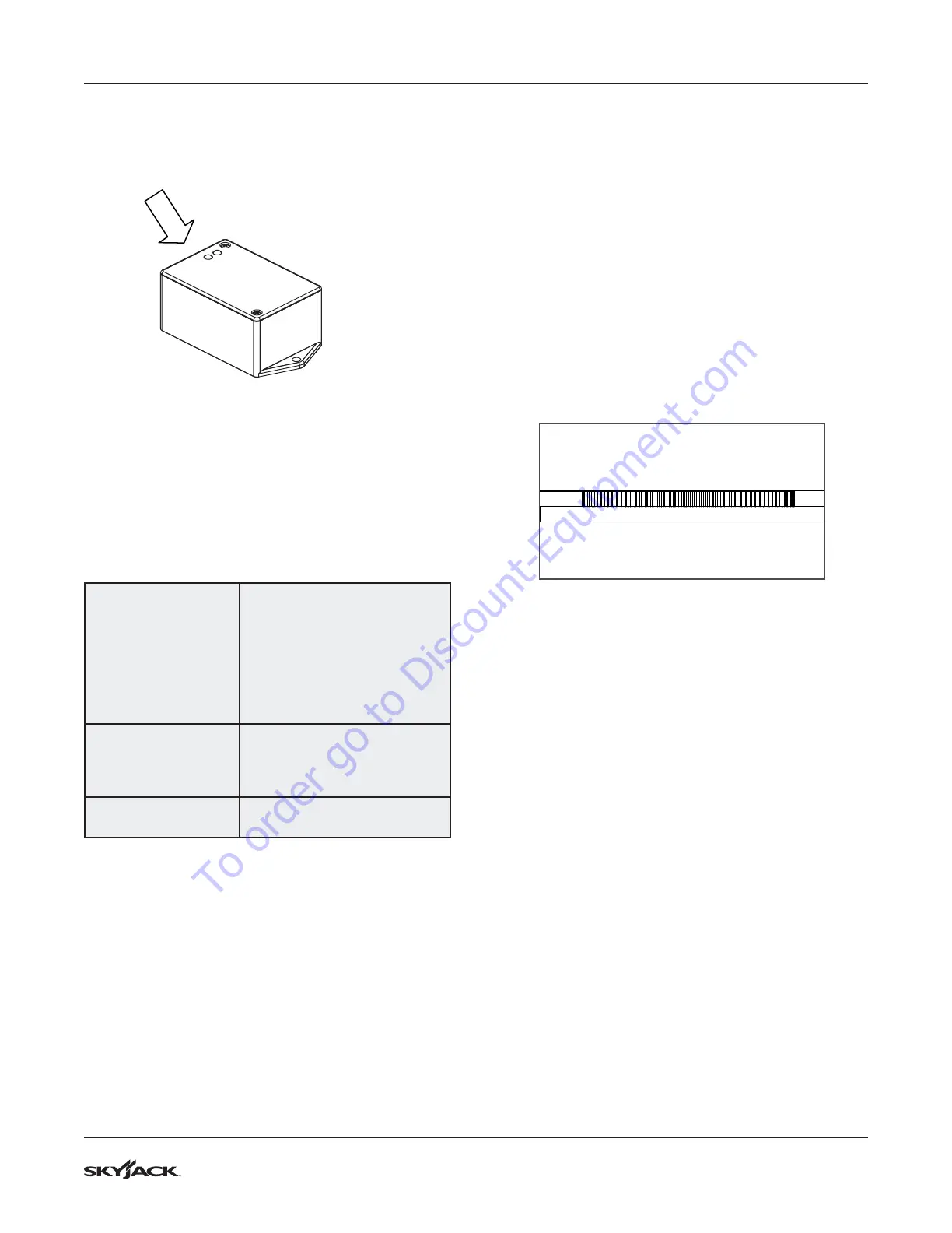
Verify the Tilt Circuit
Red LED
Green LED
Indicator Lights
Operations of the Tilt Switch
The following describes the LEDs and what they
indicate.
Green LED
Illuminated whenever both tilt
axes are within the specified
degrees of the zero/ home
learned position.
Flashes when transitioning in
or out of tilt angle limits, but
built in time delay has not fully
occurred.
Red LED
Illuminated whenever tilt on
one or more axes is more than
the specified degrees out from
the zero/ home position.
Green & Red LED
On together, no blinking when
fault detected.
5.5-8 Check the Rotation Bearing for
Axial Wear
1. Position the boom so it is centered over the front
drive and steer axle and is horizontal with the
ground.
2. Extend the boom to its full extension length.
3. Mount a dial indicator on the chassis. Place
the dial indicator set directly under the boom,
close to the bearing teeth. Make sure to allow
clearance as the turret assembly rotates.
4. Position the indicator arm or shaft so the
pointer touches the bottom surface of the turret
weldment.
CHASSIS
TURRET
5. Zero the dial indicator.
6. Rotate the turret 180° in the clockwise direction
until the boom is centered over the rear axle
(rotating the turret in the counterclockwise
direction will cause the rotation gearbox pinion
to impact the dial indicator).
7. If, when you are rotating the turret the boom
needs to be retracted or raised to avoid
obstacles, be sure to again fully extend and
level the boom when it is positioned over the
rear axle. Do not be concerned with any dial
indicator readings as the turret assembly rotates.
8. With the boom assembly rotation stopped and
the boom centered over the rear axle, read
the dial indicator and record the reading. This
reading is the total amount of axial movement in
the bearing assembly. If this reading is 2.54 mm
(0.100") or greater, the rotation bearing should
be removed and replaced.
To order go to Discount-Equipment.com
 Loading...