198
Section 5 – Procedures Manifolds and Hydraulic Pumps
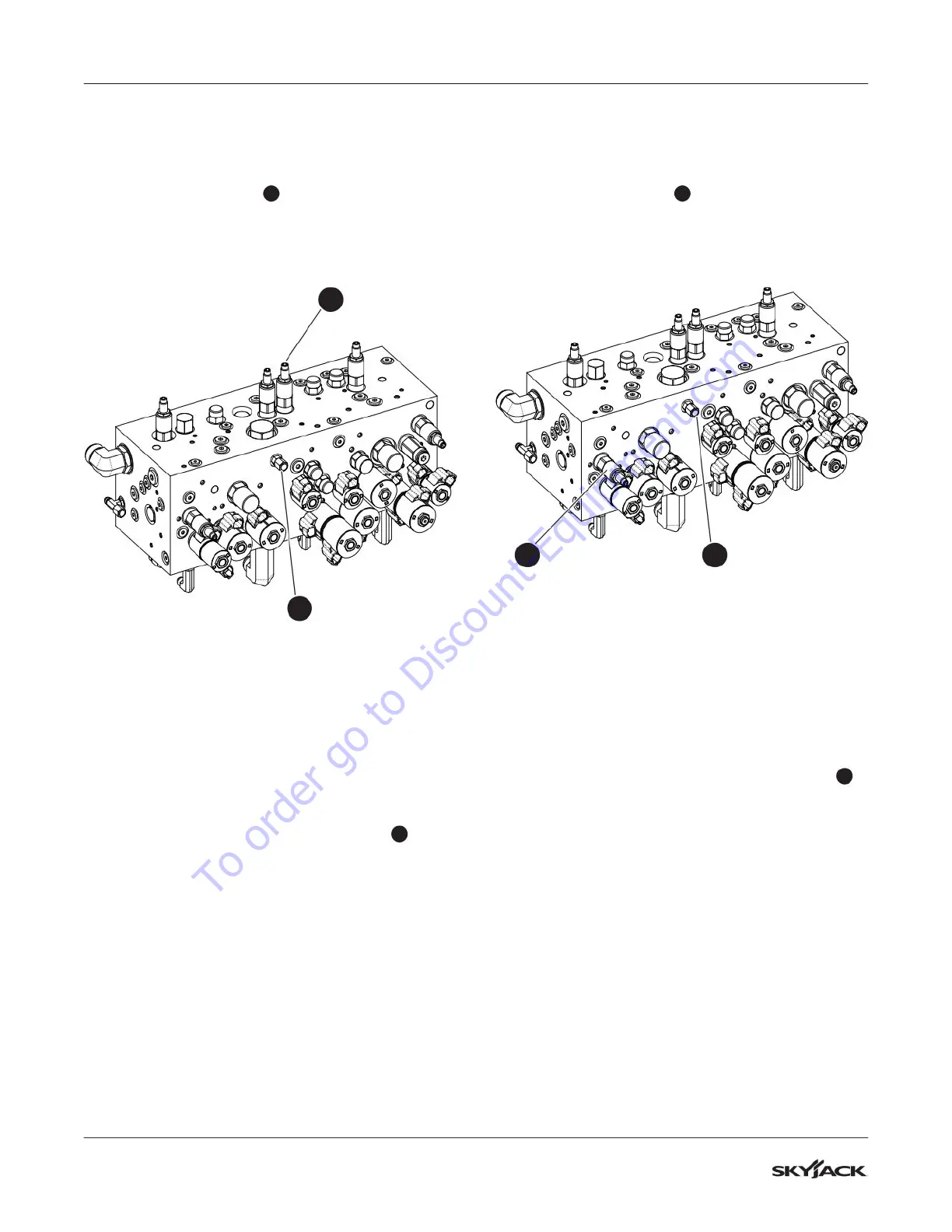
5.8-5 Turret Rotate Relief Valve
Adjustment
1. Locate the GP1 port
1
on the main manifold.
2. Connect a pressure gauge (345 bar / 5000 psi)
to the GP1 port.
1
3
3. Start the engine from the base control console
and let it run for 2-5 minutes.
4. Raise the main boom to ensure the basket will
not contact the ground.
5. Engage the turret transport lock.
6. Attempt to rotate the turret. The pressure should
be 120 bar (1750 psi). Follow the next steps for
adjusting the pressure, if needed.
7. Locate the turret rotate relief valve RV2
3
.
8. Loosen the lock nut on the turret rotate relief
valve RV2. Turn the adjusting stem clockwise to
increase the pressure and counterclockwise to
decrease the pressure.
9. Tighten the lock nut on the turret rotate relief
valve RV2 once 120 bar (1750 psi) is observed
on the gauge. You must activate the turret rotate
to obtain a pressure reading on the gauge.
10. Disengage the turret transport lock.
5.8-6 Platform Level Relief Valve
Adjustment
1. Locate the GP1 port
1
on the main manifold.
2. Connect a pressure gauge (345 bar / 5000 psi)
to the GP1 port.
14
3. Start the engine from the base control console
and let it run for 2-5 minutes.
4. Raise the main boom to ensure the platform will
not contact the ground.
5. Fully raise or lower the platform level and check
the reading on the gauge. The pressure should
be 206 bar (3000 psi). Follow the next steps for
adjusting the pressure, if needed.
6. Locate the platform leveling relief valve RV3
4
.
7. Loosen the lock nut on the platform level relief
valve RV3. Turn the adjusting stem clockwise to
increase the pressure and counterclockwise to
decrease the pressure.
8. Tighten the lock nut on the platform level relief
valve RV3 once 206 bar (3000 psi) is observed
on the gauge. You must fully raise or lower the
platform level to activate a pressure reading on
the gauge.
To order go to Discount-Equipment.com
 Loading...