199
Manifolds and Hydraulic Pumps Section 5 – Procedures
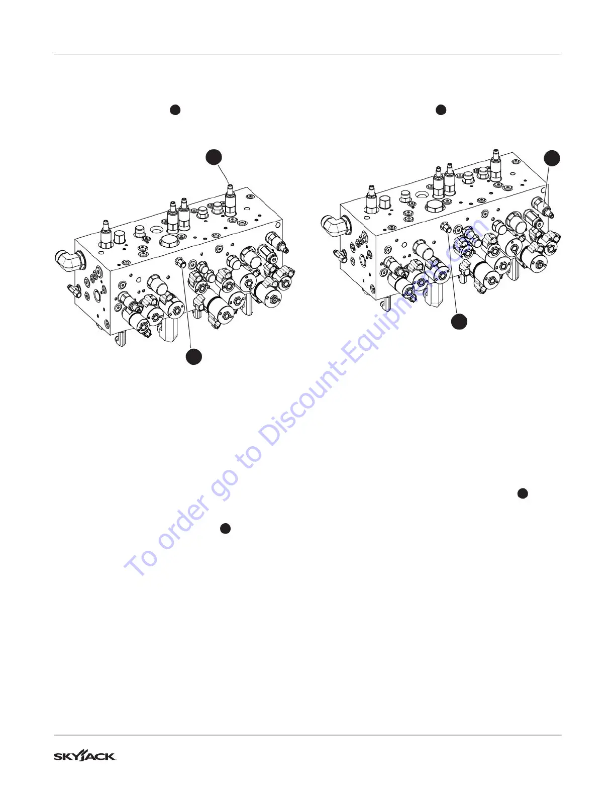
5.8-7 Riser Relief Valve Adjustment
1. Locate the GP1 port
1
on the main manifold
and remove the cap.
1
5
2. Connect a pressure gauge (345 bar / 5000 psi)
to the GP1 port.
3. Start the engine from the base control console
and let it run for 2-5 minutes.
4. Raise the jib boom so the platform will not touch
the ground.
5. Fully lower the riser and check the reading on
the gauge. The pressure should be 138 bar
(2000 psi). Follow the next steps for adjusting
the pressure, if needed.
6. Locate the riser relief valve RV4
5
.
7. Loosen the lock nut on the riser boom relief
valve RV4. Turn the adjusting stem clockwise to
increase the pressure, and counterclockwise to
decrease the pressure.
8. Tighten the lock nut on the riser boom relief
valve RV4 once 138 bar (2000 psi) is observed
on the gauge. You must fully lower the riser to
activate a pressure reading on the gauge.
5.8-8 Main Boom Relief Valve Adjustment
1. Locate the GP1 port
1
on the main manifold
and remove the cap.
1
6
2. Connect a pressure gauge (345 bar / 5000 psi)
to the GP1 port.
3. Start the engine from the base control console
and let it run for 2-5 minutes.
4. Raise the jib boom so the platform will not touch
the ground.
5. Fully lower the main boom and check the
reading on the gauge. The pressure should be
172 bar (2500 psi). Follow the next steps for
adjusting the pressure, if needed.
6. Locate the main boom relief valve RV5
6
.
7. Loosen the lock nut on the main boom relief
valve RV5. Turn the adjusting stem clockwise to
increase the pressure, and counterclockwise to
decrease the pressure.
8. Tighten the lock nut on the main boom relief
valve RV5 once 120 bar (1750 psi) is observed
on the gauge. You must fully lower the riser to
activate a pressure reading on the gauge.
To order go to Discount-Equipment.com
 Loading...