LD301 – Operation and Maintenance Instruction Manual
6.8
Notes
(1) Meets NACE MR – 01 – 75/ISO 15156 recommendations.
(2) Without explosion proof or intrinsic safety approvals.
(3) Only available for differential and gage pressure models.
(4) Values limited to 4 1/2 digits, unit limited to 5 characters.
(5) Degrease cleaning not available for carbon steel flanges.
(6) Not applicable for saline atmosphere.
(7) IP66/68W tested for 200 hours according to NBR 8094 / ASTM B 117 standard.
(8) IPX8 tested in 10 meters of water column for 24 hours.
(9) Ingress Protection:
Product CEPEL NEMKO/EXAM FM CSA NEPSI
LD300 IP66/68W IP66/68W Type4X/6(6P) Type4X IP67
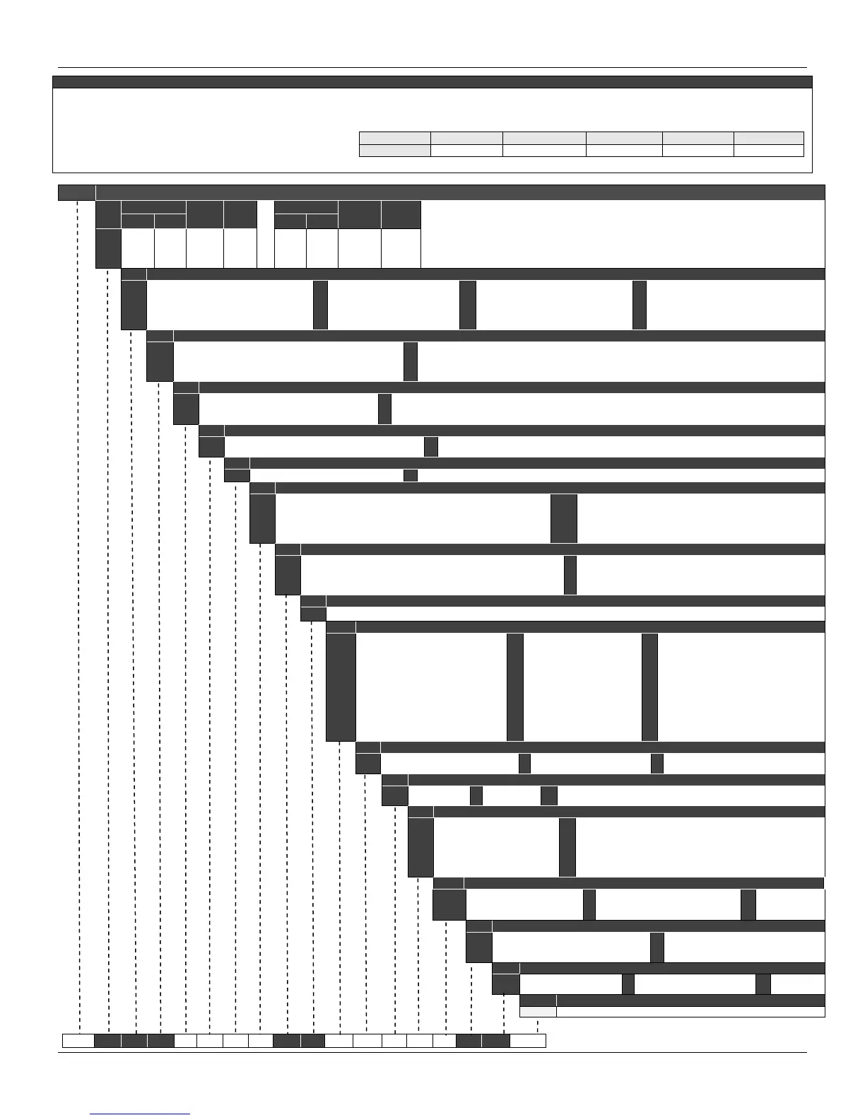
MODEL FLANGED PRESSURE TRANSMITTER
COD.
Range Limits
Min.
Span
Unit
Range limits
Min.
Span
Unit
Note: The range can be extended up to 0.75 LRL and 1.2 URL with small degradation of accuracy. The
upper range value must be limited to the flange rating.
Min. Max. Min. Max.
L2
L3
L4
L5
-50
-250
-2500
-25000
50
250
2500
25000
1.25
2.08
20.83
208.3
kPa
kPa
kPa
kPa
-200
-14,7
-14,7
-14,7
200
36
360
3600
0,42
2,08
20,83
0,21
inH
2
O
psi
psi
psi
COD.
Diaphragm material and Fill Fluid (Low Side)
1
2
3
4
5
316L SST
316L SST
Hastelloy C276
Hastelloy C276
Monel 400
Silicone Oil (2)
Inert Oil Fluorolube(3)(21)
Silicone Oil (1) (2)
Inert Oil Fluorolube (1)(3)(21)
Silicone Oil (1) (2)
7
8
9
A
D
Tantalum
Tantalum
316L SST
Monel 400
316L SST
Silicone Oil (2)
Inert Oil Fluorolube (3) (21)
Fomblim Oil
Fomblim Oil (1)
Inert Oil Krytox (21)
E
G
K
M
P
Hastelloy C276
Tantalum
Monel 400
Monel 400 Gold Plated
Monel 400 Gold Plated
Inert Oil Krytox (1)(21)
Inert Oil Krytox (21)
Inert Oil Krytox (1) (21)
Silicone Oil (1) (2)
Inert Oil Krytox (1) (21)
Q
R
S
316L SST
Hastelloy
C276
Tantalum
Inert Oil Halocarbon 4.2 (21)
Inert Oil Halocarbon 4.2 (1) (21)
Inert Oil Halocarbon 4.2 (21)
COD.
Flange, Adapter and Drain/Vent Valves material (Low Side)
A
C
H
I
304L SST
Plated CS (Drain/Vent in Stainless Steel) (22)
Hastelloy C276 (CW – 12MW, ASTM – A494) (1)
316 SST – CF8M (ASTM – A351)
M
N
P
Monel 400 (1)
316 SST – CF8M (ASTM – A351) (Drain/Vent in Hastelloy C276) (1)
316 SST – CF8M (ASTM – A351) Flange with PVDF (Kynar) insert (3) (4) (5)
COD.
Wetted O’Ring Material (Low Side)
0
B
E
Without O’Rings
Buna-N
Ethylene - Propylene
K
T
V
Kalrez
Teflon
Viton
Note: O’rings are not available on the sides with remote seals.
COD.
Drain/Vent Position (Low Side)
0
A
Without Drain/Vent
Drain/Vent (Opposite to Process Connection)
D
U
Bottom
Top
Note: For better Drain/Vent operation, vent valves are strongly
recommended. Drain/Vent valve are not available on the sides with remote seals.
COD.
Local Indicator
0
Without Indicator 1 With Digital indicator
COD.
Process Connection (Low Side)
0
1
3
5
9
1/4 - 18 NPT (Without Adapter)
1/2 - 14 NPT (With Adapter)
Remote Seal (With Plug ) (7)
1/2 - 14 NPT Axial with PVDF Insert (3) (4) (6)
Remote Seal (Low Volume Flange) (3) (7)
T
U
V
W
1/2 14 BSP (With Adapter)
Low Volume Flange For Level Welded
Without Connection (Mounting With Gage Flange)
Without Connection (Absolut Reference)
COD.
Electrical Connection
0
1
2
3
1/2 – 14 NPT (27)
3/4 – 14 NPT (with 316 SST adapter for ½ - 14 NPT) (24)
3/4 – 14 BSP (with 316 SST adapter for ½ - 14 NPT) (9)
1/2 – 14BSP (with 316 SST adapter for ½ - 14 NPT) (9)
B
Z
M20 x 1.5 (28)
PG 13.5 DIN (28)
User’s specification
COD.
Zero and Span Adjust
1 With Zero and Span Adjustment
COD.
Process Connection
U
V
W
O
P
Q
9
A
B
1
2
1” 150 # (ANSI B16.5) (31)
1” 300 # (ANSI B16.5) (31)
1” 600 # (ANSI B16.5) (31)
1.1/2” 150 # (ANSI B16.5)
1.1/2” 300 # (ANSI B16.5)
1.1/2” 600 # (ANSI B16.5)
2” 150 # (ANSI B16.5)
2” 300 # (ANSI B16.5)
2” 600 # (ANSI B16.5)
3” 150 # (ANSI B16.5)
3” 300 # (ANSI B16.5)
C
N
3
4
D
5
R
E
6
7
8
3” 600 # (ANSI B16.5)
3” 600 # (ANSI B16.5 RTJ)
4” 150 # (ANSI B16.5)
4” 300 # (ANSI B16.5)
4” 600 # (ANSI B16.5)
DN25 PN 10/40 (31)
DN 40 PN 10/40
DN 50 PN 10/40
DN 80 PN 10/40
DN 100 PN 10/16
DN 100 PN 25/40
S
F
T
K
G
L
H
M
Z
JIS 40A 20K (25)
JIS 50A 10K (25)
JIS 50A 40K (25)
JIS 50A 20K (25)
JIS 80A 10K (25)
JIS 80A 20K (25)
JIS 100A 10K (25)
JIS 100A 10K (25)
User’s specification
COD.
Type and Flange Material ( Level Tap)
2
3
316L SST (Integral Flange)
Hastelloy C276 (Integral Flange)
4
5
304 SST (Slip-on Flange)
316 SST (Slip-on Flange)
6
Z
Carbon Steel (Slip-on Flange)
User’s specification
COD.
Extension Length
0
1
0 mm (0”)
50 mm (2”)
2
3
100 mm (4”)
150 mm (6”)
4
Z
200 mm (8”)
User’s specification Note: Extension Material 316L SST
COD.
Diaphragm Material / Extension (Level Tap)
1
2
3
4
5
304L SST / 304L SST
316L SST / 316 SST
Hastelloy C276 / 316 SST
Monel 400 / 316 SST
Tantalum / 316 SST (10)
Titanium / 316 SST (10)
6
7
B
L
C
316L SST with Teflon Lining (For 2”and 3”)
316L SST Gold plated
Tantalum with Teflon Lining
316L SST Halar Plated (20)
Hastelloy Teflon Plated
COD.
Fill Fluid
1
3
2
DC – 200/20 Silicone Oil
DC704 Silicone Oil
MO – 10 Fluorolube Oil (8)
4
N
G
Krytox Oil
Neobee M20 Propylene Glycol Oil
Glycerin (6)
B
H
T
Fomblim 06/06
Halocarbon 4.2
Syltherm 800 Oil
COD.
Housing Material
0
1
2
Without Gaskets (12)
316 SST
Hastelloy C276
3
4
5
Super Duplex (UNS 32750) (11)
Duplex (UNS 31803) (11)
Stainless Steel 304L (11)
COD.
Gasket Material
0
T
Without gasket
Teflon (PTFE)
G
C
Grafoil (Flexible lead)
Copper
I 316 L SST
COD.
Continues Next Page
TYPICAL MODEL NUMBER
LD301 L2 1 I B U 1 0 0 1 1 2 2 1 1 1 T