-16-
No.EX※※-OMX1011
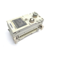
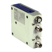
SI Unit
Model Indication and How to Order
Output type / Number of ports
PNP (negative common) / 2 port
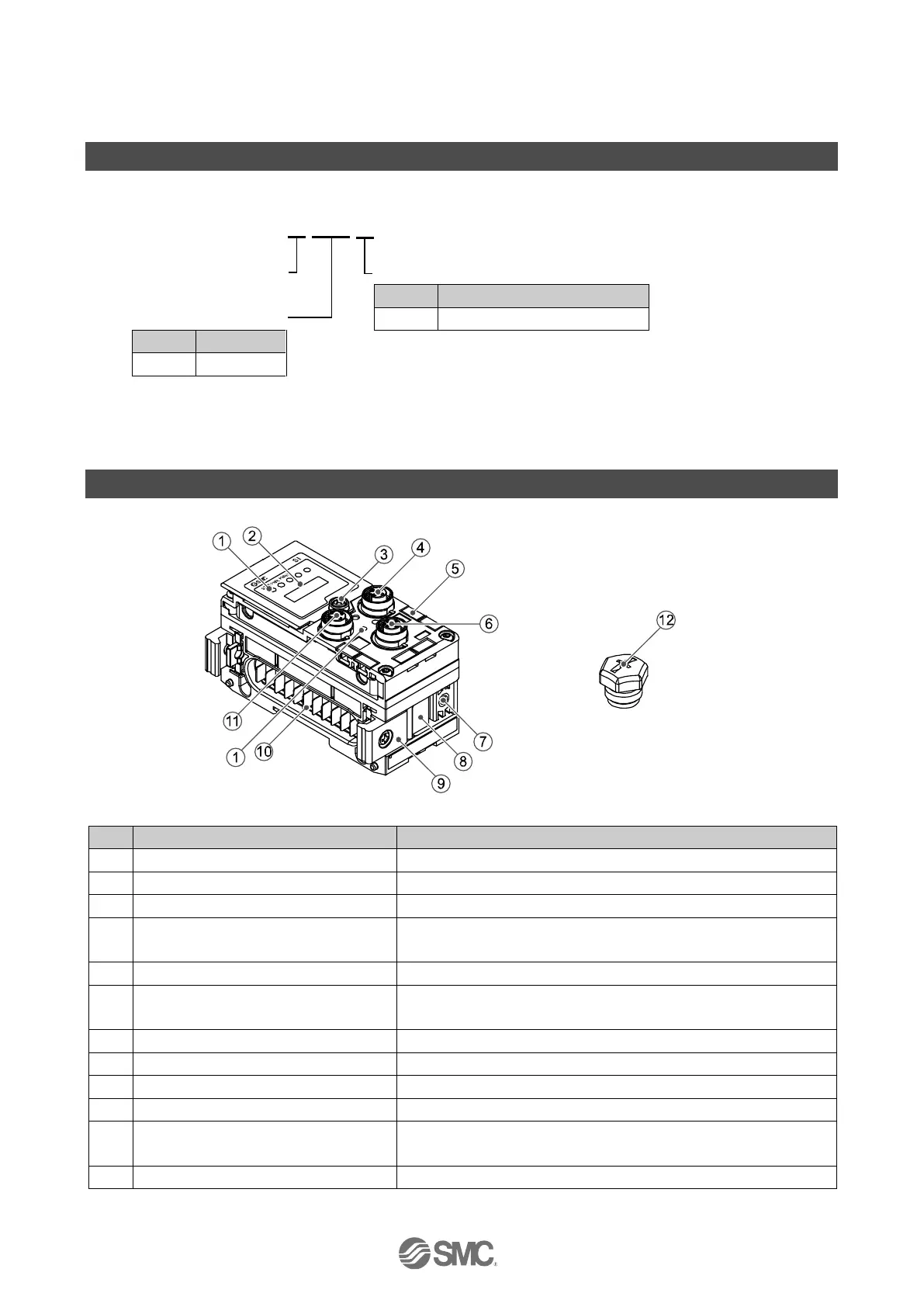
Displays the status of the unit.
Open at the switch configuration.
Display cover tightening screw
Loosen to open the display cover.
Connects the cable for fieldbus outputs.
(M12, 5 pin, socket: SPEEDCON)
Groove to mount a marker.
Connects the cable of the handheld terminal.
(M12, 5 pin, socket: SPEEDCON)
Valve plate mounting screw hole
Valve plate mounting groove
Groove to insert the valve plate into.
Bracket for joining to adjacent units.
Transmits signals and power supplies to adjacent units.
Connects the cable for fieldbus inputs.
(M12, 5 pin, socket: SPEEDCON)
Mounted on to unused connectors (BUS OUT and PCI).

 Loading...