-22-
No.EX※※-OMX1011
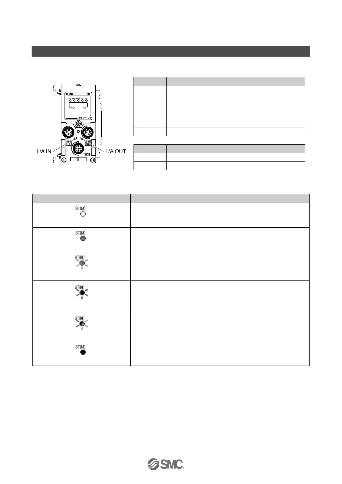
LED Display
LED display shows the power supply and communication status.
Displays the diagnosis status of the unit.
Displays the status of the power supply voltage for control
and input.
Displays the status of the power supply voltage for output.
Displays the module status.
Displays the network status.
Displays the communication status of the BUS IN side.
Displays the communication status of the BUS OUT side.
The power supply for control and input is OFF.
Diagnostic error of I/O unit is detected.
Either of the following diagnostic error is detected.
(When diagnostic parameter is enabled)
•Valve ON/OFF counter has exceeded the set value.
•Valve is short circuited or disconnected.
Red/green flashing alternately
Detect a communication error between SI unit and I/O unit.

 Loading...