- 9 -
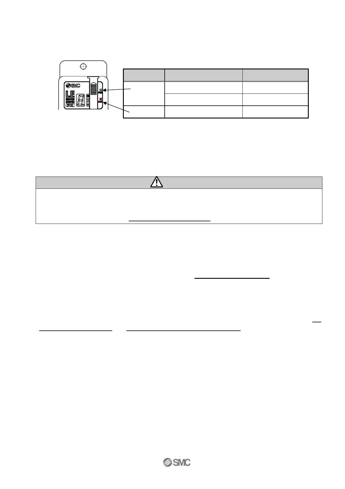
(4) Power supply ON Alarm check
Supply power 24V DC.
Description LED turns on Condition
Green LED is on Servo is on PWR
Green LED is flashing Servo is turned off
ALARM Red Alarm is generated
If the conditions are normal, the LED[PWR] at the front of the controller switches from a flashing to a
solid light. The servo is turned on if the conditions are normal. If the LED[ALM] on the front surface of
the controller turns red, the alarm goes off.
Caution
When an alarm is generated
Confirm the content of the alarm with 7-segment LED of the controller or I/O output.
Eliminate the cause referring to
12. Alarm detection (P
.59)
.
(5) Data (Operation pattern) setting
Set the stop position, speed, acceleration, and deceleration for the operating directions with the
buttons and switches on the controller. Operations other than position setting, jog/inching can be
performed after returning to origin position. Refer to
7. Setting method (P.
23)
for the details of
settings.
(6) Test run
Test run is performed with the buttons and switches of the controller or I/O signal. Refer to
7.1
Setting procedure (P.
24)
and
6.3 Parallel input / output signal (P.
20)
for details.
Controller

 Loading...


