- 45 -
9.2 Pushing operation
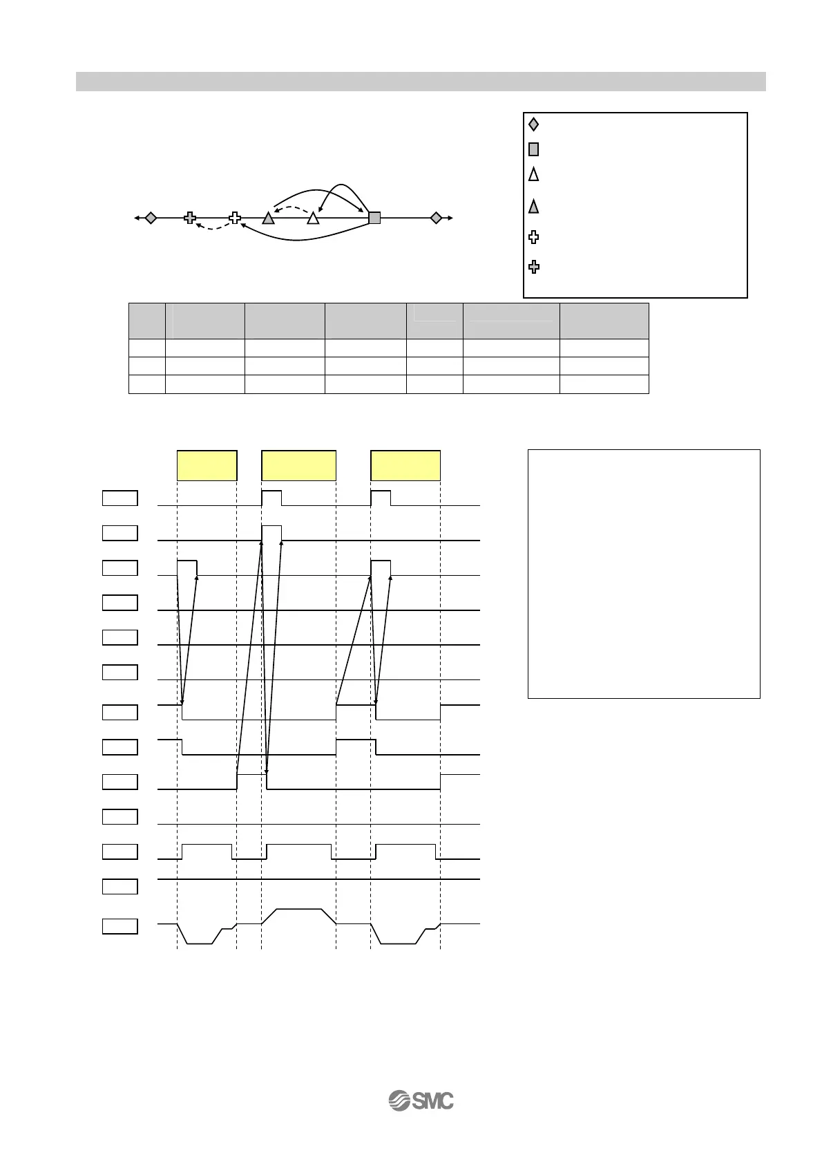
Ex.) If the operation pattern is Position 3 --> Position 4 --> Position 3 --> Position 5.
Forward: Speed 5, acceleration 3 (Switch value)
Reverse: Speed 9, acceleration 7 (Switch value
Start
position
End
position
Operating
direction
speed acceleration Operation
method
(1) NO.3 NO.4 Reverse 9 7 Pushing
(2) NO.4 NO.3 Forward 5 3 Positioning
(3) NO.3 NO.5 Reverse 9 7 Pushing
Example) I/O timing chart when the actuator is operated by PLC
<Procedure>
[1] When OUT0 and 1 turn on, turn ON
IN2 and start operation(1) to
position No.4.
[2] BUSY turns ON when the
operation starts, and OUT0 and
1 turn OFF.
[3] When BUSY turns ON, turn OFF
IN2.
[4] BUSY turns OFF when the
operation is completed, and
OUT2 turns ON.
[5] Do the same for the travel for
position No.3 and position No.5.
IN1
ON
OFF
IN2
ON
OFF
IN3
ON
OFF
RESET
ON
OFF
bit_1
IN2
(2)
To NO.3
OUT0
ON
OFF
OUT1
OFF
ON
OUT2
ON
OFF
OUT3
ON
OFF
BUSY
OFF
ON
bit_0
bit_1
bit_2
bit_3
(1)
To NO.4
IN0
OFF
ON
STOP
ON
OFF
bit_0
bit_2
bit_3
LAR
OFF
ON
Speed
0
+
-
(3)
To NO.5
Position NO.3
Position NO.4
Position NO.5
Actuator end
Position at which pushing to
the reverse direction from
osition No.4 is com
leted
Position at which pushing to the
reverse direction
from position No.5 is completed
forward
direction
Reverse
direction
(1)
(2)
(3)

 Loading...


