EasyManuals Logo
Home>SMC Networks>Controller>LECP1 Series

SMC Networks LECP1 Series User Manual

SMC Networks LECP1 Series
76 pages
To Next Page IconTo Next Page
To Previous Page IconTo Previous Page
Page #8 background imageLoading...
Page #8 background image
- 7 -
PLC
Input/output signal
p
ower su
pp
l
y
Controller input
power supply
24VDC
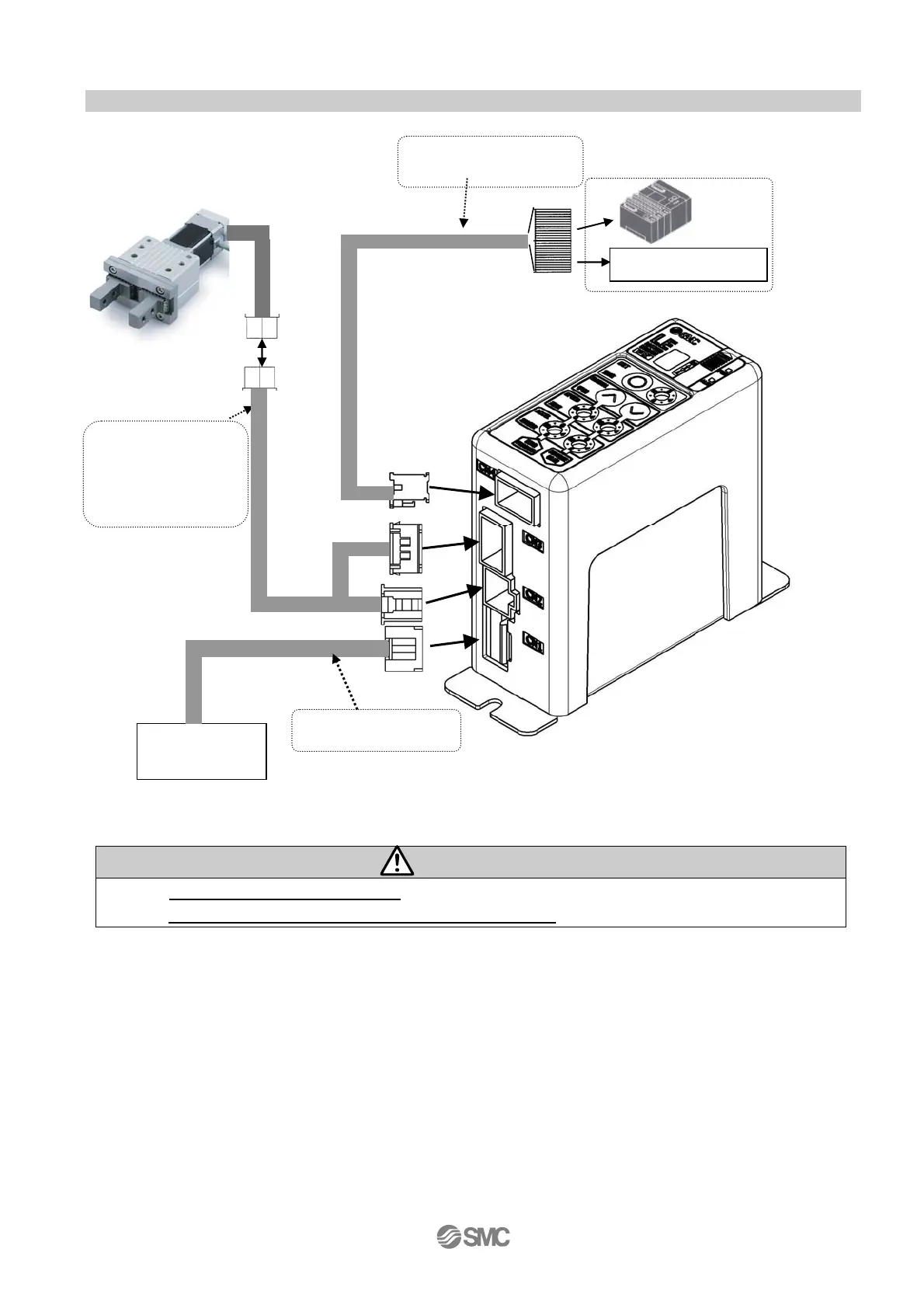
2.3 Structure of the product
Structure of the controller.
* These items are included if you ordered using the part number for an actuator set.
Warning
Refer to 4. External connection (P.15) for wiring.
Refer to 13. Wiring of cables/Common precautions (P.
63) when handling the wiring and cables.
*
Electric actuator
To CN 4
To
CN1
To CN 2
To CN 3
I/O cable
Part no.: LEC-CK4-*
*
Controller
*
Actuator cable
[Robot cable]
Part no.: LE-CP-*
[Standard cable]
Part no. :LE-CP-*S
Power supply cable
Part no.: LEC-CK1-1

Table of Contents

Other manuals for SMC Networks LECP1 Series

Questions and Answers:

Question and Answer IconNeed help?

Do you have a question about the SMC Networks LECP1 Series and is the answer not in the manual?

SMC Networks LECP1 Series Specifications

General IconGeneral
BrandSMC Networks
ModelLECP1 Series
CategoryController
LanguageEnglish

Related product manuals