- 15 -
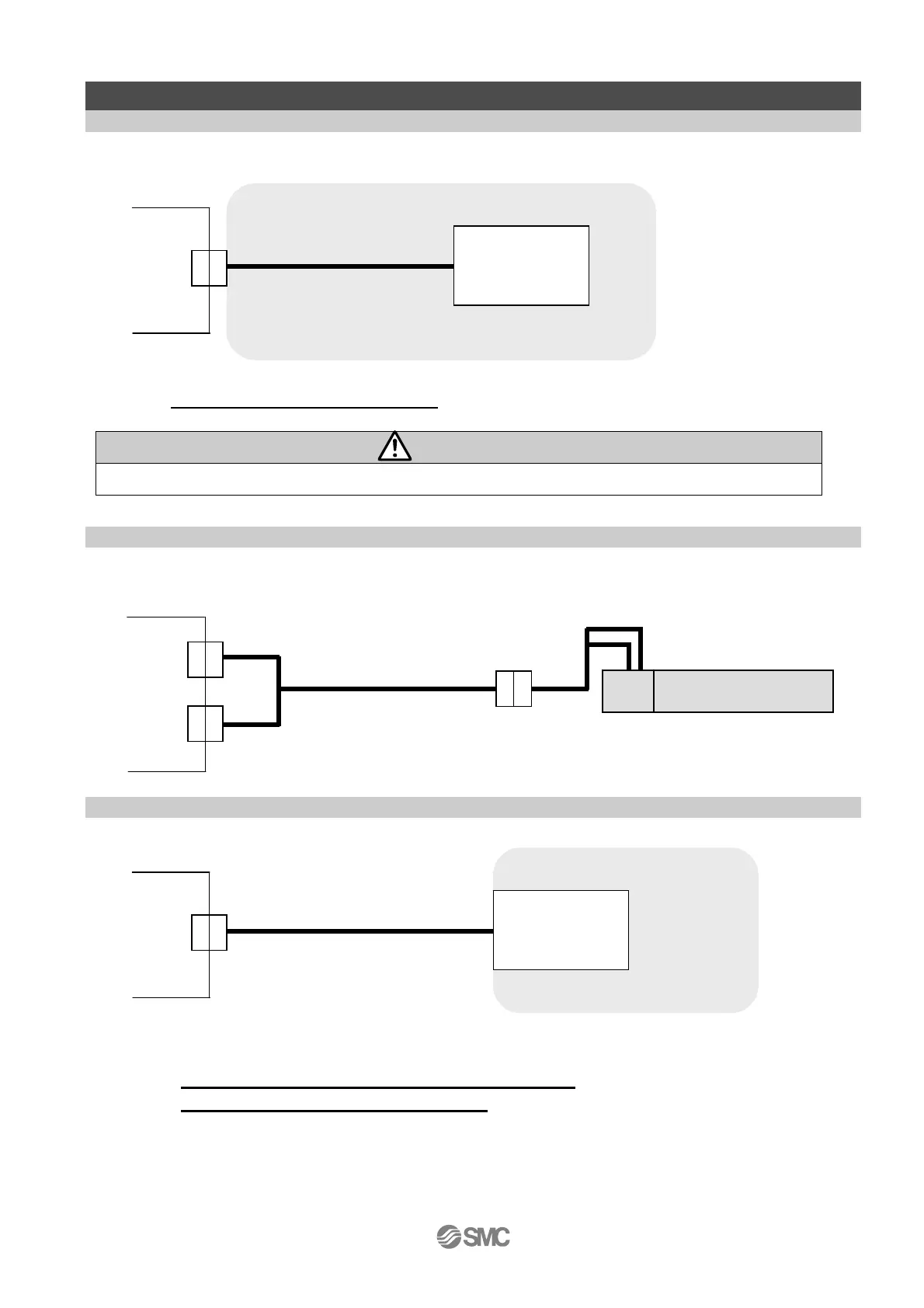
4. External connection
4. 1 CN1: Power supply connector
The example of standard wiring of the controller is shown per connector (CN1 to 4).
Refer to 5. CN1: Power supply cable(P.16) for wiring.
Caution
Do not use inrush current suppressor type as the power supply for the controller input.
4. 2 CN2: Motor connector, CN3: Encoder connector
Connect the controller and the actuator with the actuator cable (LE-CP-□ or LE-CP-□S).
4. 3 CN4: Parallel I/O connector
* Refer to 6.4 Parallel I/O connector wiring (Example) (P.22) for wiring.
* Refer to 6.3 Parallel input / output signal (P.
20) for details
Controller
Actuator cable
CN2
CN3
Actuator
Motor
Controller
CN1
Controller input
power supply 24VDC
(Controller input power supply of 24V DC is prepared by
customer.
Power su
l
cable
Controller
CN4
PLC etc.
(PLC is prepared by customer)
I/O cable

 Loading...


