36
Scanner Operations Operations
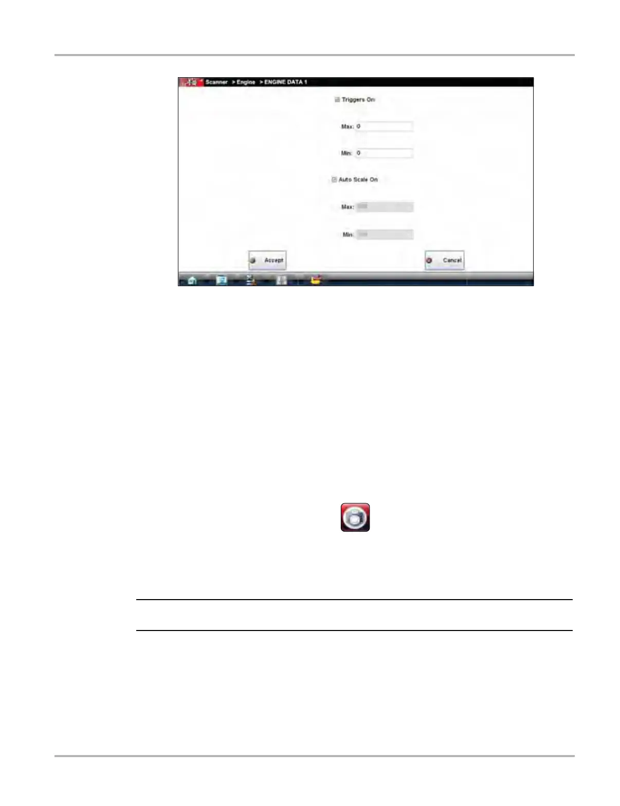
Figure 5-15 Sample Graph Properties dialog box
3. Tap either Max: (maximum) or Min: (minimum) to activate that field and open the keyboard.
4. Type the desired trigger value into the field.
5. Tap the other field and enter a trigger value, then close the virtual keyboard.
6. Tap Accept to close the dialog box.
Trigger lines (red for upper and blue for lower) display on the selected parameter graph.
The area between the upper and lower trigger lines establishes the triggering condition. Once
the snapshot is armed, any data points that register outside of the set trigger conditions
initiates a snapshot. The Scanner continues to record the preset amount of data after the
trigger and includes it in the snapshot.
7. Tap Snapshot on the Data Buffer Toolbar to arm the snapshot.
A red background appears on the Snapshot button to indicate it has been armed
(Figure 5-16).
Figure 5-16 Sample armed Snapshot button
The data capture pauses when a trigger activates.
8. Tap the Play button on the toolbar to resume viewing live data.
i Selecting an armed Snapshot button disarms it.
Scale
Scale adjusts the upper and lower values displayed on the vertical axis of a data graph. Two scale
modes are available; auto scale and manual scale. Auto scale, which is the default setting,
automatically adjusts the graph scale based upon the minimum and maximum values transmitted
by the ECM. Manual scale allows you to set the minimum and maximum values.
 Loading...