31
EN
ATySpM - 542935E - SOCOMEC
13. OPERATION
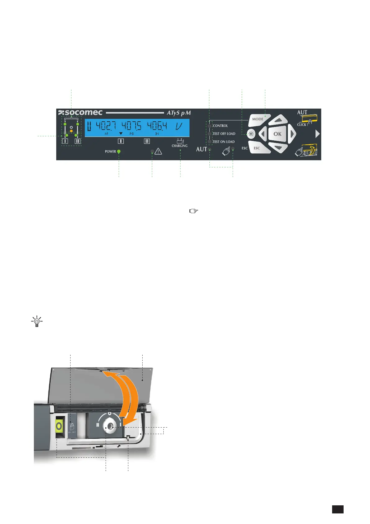
13.1. Presentation of the product interface
The LED signalling is only active when the product supply is on (supply LED lit)
6789
1
2 543
1. Availability of sources
• 2 green LEDs to indicate whether source I and/or source II
are available (voltages and frequencies check).
- LED lit = source available.
- LED off = source unavailable.
2. Position of the switch
• 2 green LEDs
- LED I lit = switch in position I
- LED II lit = switch in position II
• 1 yellow LED
- LED lit = switch in position 0
3. Test/Control modes
• 2 yellow LEDs for the test on load and test off load which
are linked to the test mode selection button so as to facili-
tate selection.
• 1 yellow LED for the control function. The user may force
the position of the switch.
4. LED test button
•
: Illuminates all LEDs to test their operation.
5. Mode button
• Test mode selection button.
6. Operating mode (Auto/Manu)
•
: 1 yellow LED for MANU mode active.
• AUT : 1 green LED for AUTO mode active.
7. Capacitor charge indicator
• Return to zero capacitor charge. When the indicator ashes,
the RETURN to 0 function is unavailable.
8. Fault LED
• 1 red LED to indicate the status of the product control fault.
Open and close the AUT/MAN cover after clearing the fault.
9. Power supply LED
• 1 green LED
- Always off: power supply off or software error if the other
indicators are operational (LED and Screen).
- Always lit: product power supply on.
1 2
5
34
1. Locking
• Option to padlock using a 1 x 8 mm max. padlock.
2. AUT/MAN cover
• Open the cover to switch to manual mode.
• Close the cover to return to automatic (remote control) mode.
• Open and close the cover to clear faults.
3. Auto/Manual mode sensor
4. Switch position indicators
• Display of position I, 0, II.
5. Manual switching
• Insert the Allen key (5.0 mm) provided and turn to switch
manually.
• Manual operation is not possible when padlocked.

 Loading...


