3.
Ifyouarenotusingthelevel:
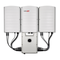
Positionthemountingbracketsagainstthewallandmarktherequireddrillingholeslocations.The
distancebetweenneighboringholesfromdifferentbracketsshouldbe9cm/3-5/8"Figure18to
ensureadistanceof1.2"(3cm)betweeninverterunits.
NOTE
Make sure to maintain the required distance between brackets and units, otherwise the cables
connecting the Secondary Unit(s) to the Connection Unit may not reach the connectors.
Figure 18: Brackets spacing
Ifyouareusingthelevel:
a. Positionthemountingbracketsagainstthewallandmarktherequireddrillingholeslocations
withthesuppliedlevel.Thelevelmarkingscorrespondtoadistanceof3cmbetweenunits.
b. Drilltwoholesforeachbracketandmountthebrackets.
c. Putinthescrewswithouttighteninginordertocorrectpositioning.
d.
Placethelevelbeneaththebracketsandalignthebrackets,tightenthescrewsallthewayand
verifythatthebracketsarefirmlyattachedtothemountingsurface.
Figure 19: Aligning the brackets
4. MountthePrimaryUnitbracketandputinthescrews.
5. TightenthePrimaryUnitscrewsallthewayandverifythatthebracketisfirmlyattachedtothe
mountingsurface.
Chapter 3: Installing the Primary and Secondary Unit(s)
-Three Phase Inverter with Synergy Technology Installation MAN-01-00402-1.4
31
 Loading...