NOTE
If you remove the old inverter and do not immediately install a new one, then:
o
Lock the StorEdge Connection Unit in the OFF position using a lock on the switch.
o
Use insulation tape to isolate each of the AC and DC wires.
o
Seal the open conduits using duct tape.
11. Placethenewinverteronthemountingbracket;insertthescrewssecuringtheinvertertothe
mountingbracket.
12. ScrewthetwoconduitnutsintheinvertersecuringtheStorEdgeConnectionUnittotheinverter.
13. ConnecttheDCandACwirestotheinverter.
14. Placetheferritebeadsonthewiresandclosethem.MakesuretheDClabeledferritebeadisplacedon
theDCwiresandtheAClabeledferritebeadisplacedontheACwires.
15. Closetheinvertercover.
16. ConfigurethesystemtotherequiredapplicationasdescribedinSystemConfigurationonpage78
17. PerformthecommissioningstepsasdescribedinCommissioningtheInstallationonpage44.
9V Battery Replacement
IfWarning8:Connection Unit Low 9V Batteryisdisplayedinthemainstatusscreen,replacethe9V
batteryintheStorEdgeConnectionUnit.
1. TurnOFFtheinverterON/OFFswitch,andwaituntiltheLCDindicatesthattheDCvoltageissafe
(<50V),orwaitfiveminutesbeforecontinuingtothenextstep.
WARNING!
If you cannot see the inverter panel, or if a malfunction is indicated on the LCD panel, wait five
minutes for the input capacitors of the inverter to discharge.
Si vous ne pouvez pas voir l'écran de l'onduleur ou si un dysfonctionnement est indiqué sur
l'écran LCD, attendez cinq minutes pour que les condensateurs d'entrée de l'onduleur soient
déchargés.
2. TurnOFFtheStorEdgeConnectionUnitandtheACswitchofthedistributionpanel.
3.
OpenandremovetheStorEdgeConnectionUnitcover.
4. Openandremovethetransparentinternalcover.
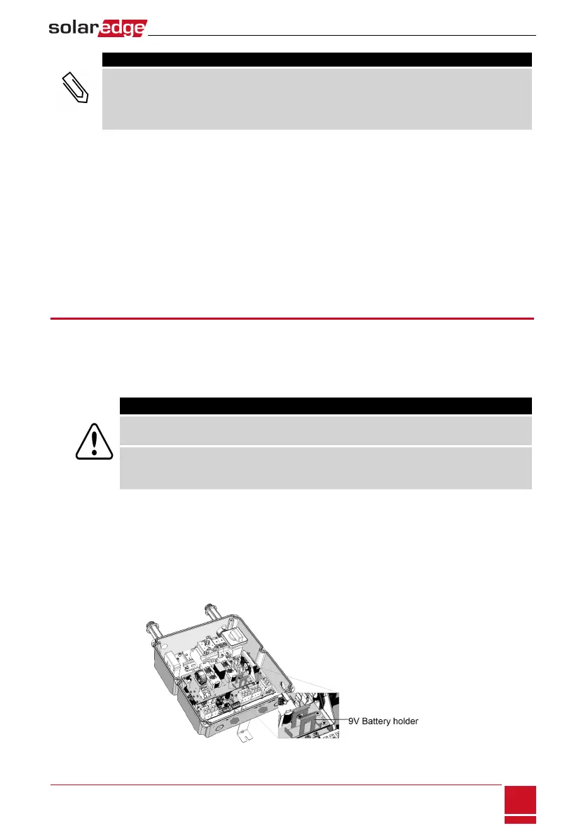
5. RemovethebatteryfromtheupperboardoftheStorEdgeConnectionUnitandreplacewithanew
standard9Vbattery.
6. ClosetheStorEdgeConnectionUnitcovers.
Figure 46: The battery holder
Appendix C: Replacing and Adding System Components
SolarEdge-StorEdge Installation Guide MAN-01-00262-1.2
99