2. TurnOFFtheStorEdgeConnectionUnitandtheACswitchofthedistributionpanel.
3. DisconnecttheDCandbatterycablesfromtheStorEdgeConnectionUnit.
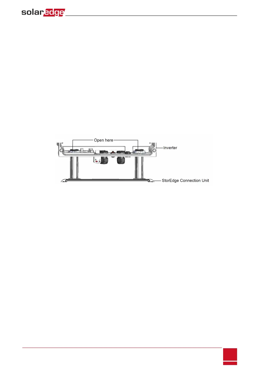
4. Opentheinvertercover.
5. DisconnecttheDCandACwiresfromtheinverter.OpentheDCandACwiresferritebeadsandset
themaside.
6. ForRGMinverter-DisconnecttheRS485connectorfromtheinvertercommunicationboard.
7. DisconnectthecableconnectingtheinverterdigitalboardtotheStorEdgeConnectionUnit.
8. UnscrewthetwoconduitnutsintheinvertersecuringtheStorEdgeConnectionUnittotheinverter.
9.
OpentheStorEdgeConnectionUnitcoveranddisconnect:
l PVDCwires
l Batterywires
l Auto-transformerwires,ifconnected
l Backed-uploadspanelwires,ifconnected
l Externalmeter,ifconnected
10.
UnscrewthetwoconduitnutssecuringtheStorEdgeConnectionUnittotheexternalconduits.
Figure 48: Conduit nuts
11. ReleasethebracketsecuringtheStorEdgeConnectionUnittothewall.
12. CarefullyremovetheStorEdgeConnectionUnitwithitsmountingbracketfromthewall.
Installing a New StorEdge Connection Unit
1. OpentheconduitknockoutsofthenewStorEdgeConnectionUnit(refertoOpeningConduit
Knockoutsonpage96).
2. OpentheStorEdgeConnectionUnitcover.
3. PositionthenewStorEdgeConnectionUnitbelowtheinverterandfromtheinsideoftheinverter
grabtheACandDCwiresextendingfromtheunitconduits.
4. AttachtheStorEdgeConnectionUnitwithitsbrackettothewallandslightlyclosethescrews.Donot
overtighten.
5. ReconnectthecablefromtheinverterdigitalboardtotheStorEdgeConnectionUnit.
6. Reconnectalltheexternalwiresandferritebeads.
7. Securelyscrewthetwoconduitnutsontotheconduitendsintheinverter.Verifyproperconduit
sealing.
8. ClosetheStorEdgeConnectionUnitcover.Attachthecoverandsecureitbytighteningthesixscrews
withatorqueof1.2N*m/0.9ft.*lb.
Appendix C: Replacing and Adding System Components
SolarEdge-StorEdge Installation Guide MAN-01-00262-1.2
101