103
Operation on LCD
Curve
PflockOutPoint
3Tua
Q(u)
SetQuPower1
SetQuPower2
SetQuPower3
SetQuPower4
QuRespondV1
QuRespondV2
QuRespondV3
QuRespondV4
K
3Tua
QuDelayTimer
QuLockEn
Fixed Q Power Q Power
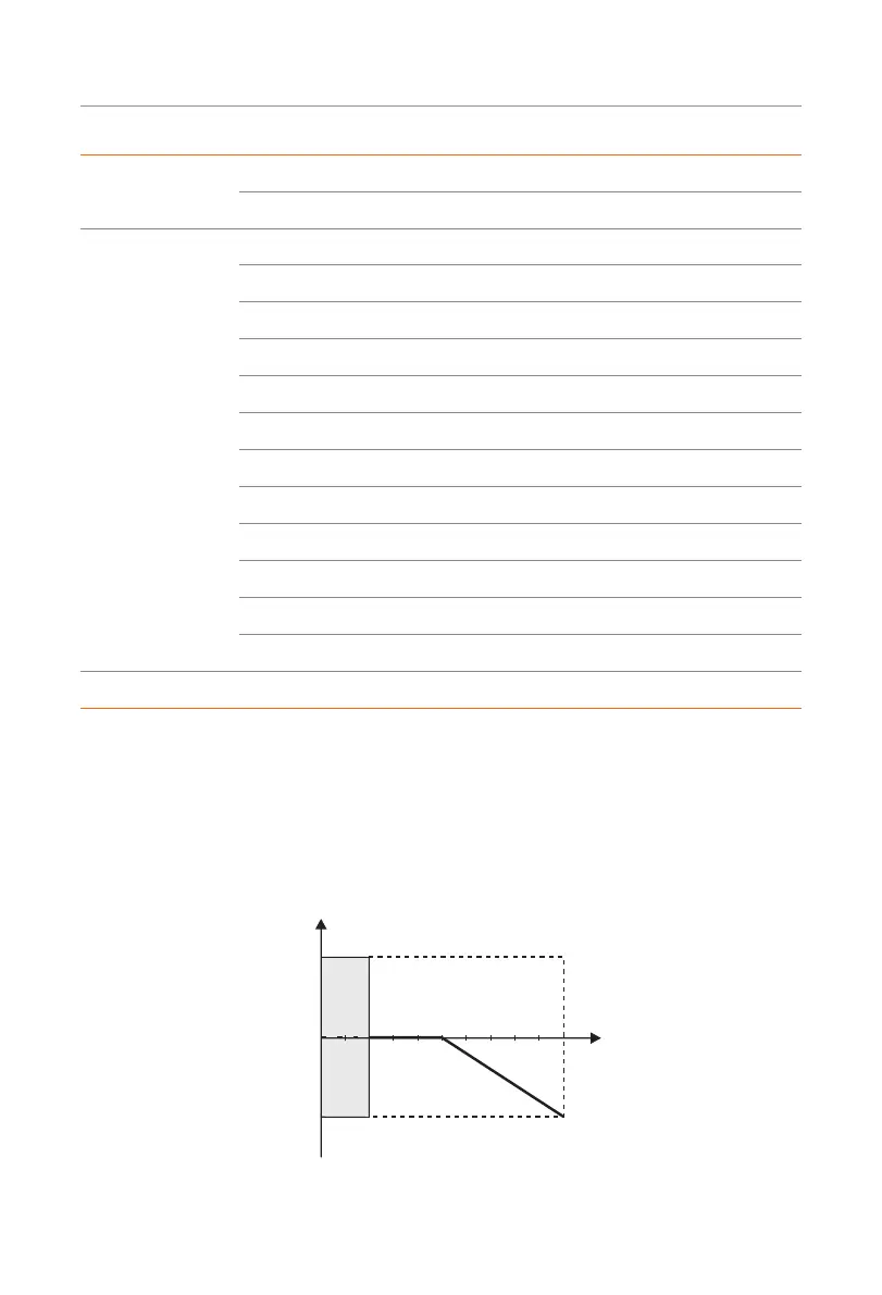
• Reactive power control, reactive power standard curve cos Ø = f(P)
»
For VDE ARN 4105, the curve cos Ø = f(P) should refer to curve A. The set
default value is shown in curve A.
»
For TOR, the curve cos Ø = f(P) should be curve B. The set default value is
shown in curve B.
»
For CEI 0-21, the default value of PFLockInPoint is 1.05. When Vac> 1.05 Vn,
Pac> 0.2 Pn, curve cos Ø = f(P) corresponds to curve C.
cos Ø
0.9/0.95 *)
0.9/0.95 *)
P/PEmax
0.2 0.5 1.0
Leading
Lagging
Over-ExictedUnder-Exicted
Curve A
»
*) If the grid-connected power of the inverter ≤ 4.6 kW, the Power Factor is
0.95 at 1.0 power; if the grid-connected power of the inverter > 4.6 kW, the

 Loading...