10 Chapter 3: System Overview
Theory of Operation
The SonoSite High-Resolution Ultrasound System (MicroMaxx) has seven (7) major functional groups:
•Transducer
•Acquisition Subsystem
• Processing Subsystem
•Display Subsystem
• Control Subsystem
• User Interface Subsystem
•Power Subsystem
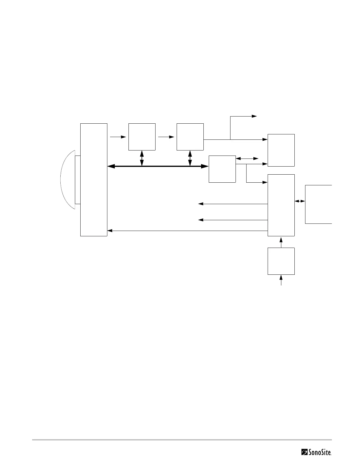
Figure 3.1 is a system block diagram that shows the relationship of the functional groups.
Figure 3.1 SonoSite High-Resolution Ultrasound System (MicroMaxx) Block Diagram
The Transducer elements convert the pulser voltage to acoustic energy during the transmit portion of the
ultrasound acquisition cycle. The elements convert the acoustic echo to voltage in the receive portion of the
acquisition. The voltage developed on the transducer elements is sensed by the acquisition subsystem. The system
transducers have 64 to 128 elements.
The Acquisition Subsystem consists of the beamformer and interface to the transducer. The beamformer times
the transmit pulses to focus the acoustic beam. The beamformer amplifies the low-level echo signal and times the
receive information to focus the receive information. The system beamformers up to 64 transmit elements and 64
receive elements.
The Processing Subsystem includes capabilities for interfacing with the beamformer and performing high speed
processing. The processing subsystem demodulates, filters, detects, and compresses the signal supplied by the
beamformer into display information.
The Display Subsystem converts the detected ultrasound data into picture elements (pixels). The software user
interface graphics are combined with the ultrasound information and converted to a video stream. The external
video port supports NTSC and PAL format.
AQ BusRF Bus
Acquisition
subsystem
Processing
subsystem
Transducer
Display
subsystem
Control Bus
Control
subsystem
User
interface
Battery
pack
assembly
Pulser voltage
Video
External video to monitor,
VCR, printer
Power
subsystem
Power
adapter
External power
IrDA
Serial Bus
Logic power
Display power