Chapter 3: System Overview 13
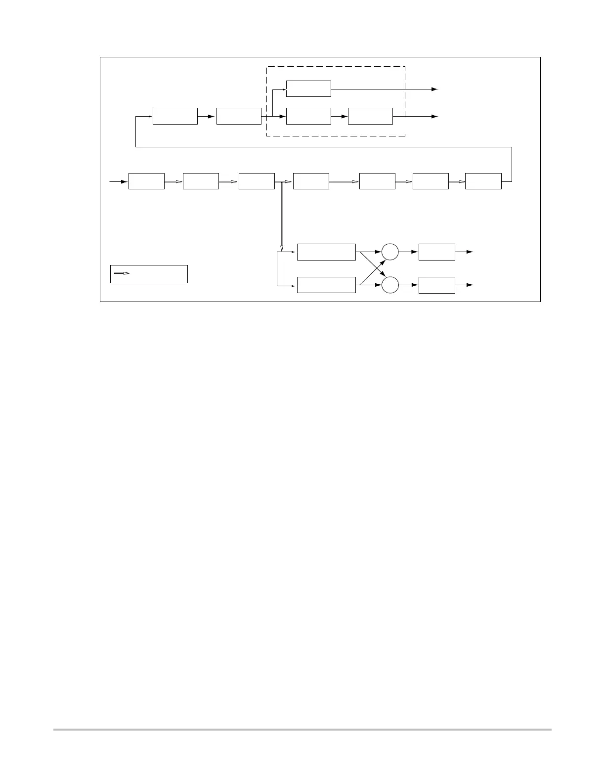
Figure 3.2 Doppler Processing Block Diagram
The Doppler processing platform can be partitioned into eight (8) blocks:
• Wall filter
• Resampler
• Hilbert phase shifter (stereo separator)
• Audio output
• Fast Fourier transformer (FFT)
• Magnitude estimation
• Temporal averaging
• Compression
Wall Filter The wall filter is a high pass filter used to remove the clutter velocity information or wall
motion signal.
Resampler Time domain Doppler samples are transformed into spectral lines using a fast Fourier
transform (FFT) technique. The resampler module does the selection of a sample set used for
computing windowed FFTs. It thus interfaces the processing thread operating at the PRF rate
with the one that computes FFT on segments of data separated at the FFT rate.
Hilbert Phase
Shifter and
Audio Output
The gain adjusted IQ stream from the wall filter is processed by a Hilbert Transformer to shift
an in-phase component by 90 degrees to present the Doppler signal as stereo audio. The 90
degree phase shift in the in-phase component is accomplished by convolving it with the
Hilbert Transform impulse response. The quadrature component data stream does not
undergo any filtering other than a delay that matches the group delay of the in-phase
channel. This is followed by a stage that computes the sum and difference of in-phase and
quadrature components to produce stereo audio data.
Fast Fourier
Transformer
This module applies a window function to the IQ sample set selected for spectral estimation
followed by the FFT. Radix 2 decimation-in-time FFT is performed using block-floating
scaling to retain maximum precision. The resulting output is later normalized during
magnitude computation.
QBP
QBP WAF RES FFT MAG
Wall
filter
128 tap FIR 128 IQ pairs
@ 1 kHz
I
Q
128 samples
@ 1 kHz
PRFPRF
Indicates IQ pairs
Post
gain
Resample Window FFT |.|
RF (PW) or Quadrature
basband input (CW)
Hilbert phase
shifter
Delay
2x16 bits @ PRF rate
+
Audio
gain
+
Audio
gain
+
+
+
_
Temporal
Averaging
Baseline
shift
Display
interpolate
Peak &
mean
AVG
Compress
CMP
128 samples
@ 50/100/200 Hz
Audio Output
Back End
DIS
128/192/256/384
samples per line