Help Guide
Color Video Camera
BRC-AM7
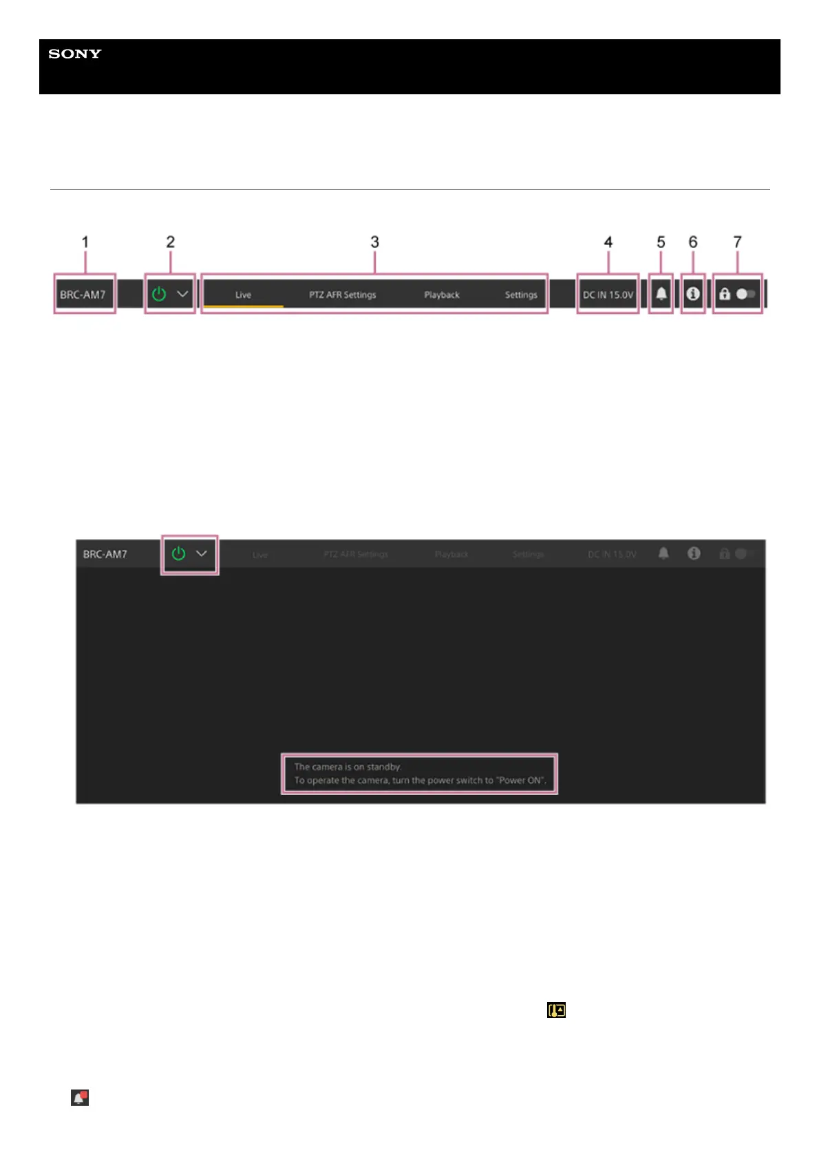
Structure of Common Area of Screens
This topic describes the structure of the common area of screens.
Camera name
Displays the name of the camera.
You can change the name using [Network] – [Camera Name] in the web menu.
The background color changes according to the external tally signal.
1.
Power switch
When the unit is turned on, a check mark is placed in [Power ON] in the switch menu.
You can press the power switch and select [Power Standby] in the switch menu to set the power supply of the unit to
standby state.
In power standby mode, the following screen appears.
To turn the power on again, press the power switch and select [Power ON] in the switch menu.
2.
Operation screen switching tabs
Press a tab to display the corresponding operation screen.
[Live] tab: Displays the live operation screen.
[PTZ AFR Settings] tab: Displays the screen used to configure the PTZ auto framing initial settings.
[Playback] tab: Displays the playback operation screen.
[Settings] tab: Displays the settings screen (web menu).
3.
DC IN voltage and abnormal temperature warning
Displays the DC IN voltage value. If an abnormal temperature condition arises, the
(Temperature warning) mark
appears.
4.
Notifications mark
When a message arrives, the mark indication changes as shown below.
(Notifications On)
5.