Help Guide
Color Video Camera
BRC-AM7
Connecting a Tally Signal
This topic describes tally signal control.
Lighting the tally lamp using a signal from a remote controller
You can light up the tally lamp using a VISCA over IP command from an external device, such as the RM-IP500.
Set [Technical] – [Tally] – [Tally Control] to [External] in the web menu or camera menu.
Lighting the tally lamp from an external device
You can light up the tally lamp of the unit red or green from an external device, such as the RM-IP500 or a switcher. You can
control the tally using commands transmitted over the network or using a tally signal input on the OPTION connector of the
unit.
Set [Technical] – [Tally] – [Tally Control] to [External] in the web menu or camera menu.
When inputting a tally signal on the OPTION connector, short-circuit pin 7 to GND (either pin 4 or 5) to light up the tally lamp
green, or pin 8 to GND (either pin 4 or 5) to light up the tally lamp red.
Note
When [Tally Control] is set to [External], the recording status of the unit is not indicated by the tally lamp.
When a red tally and green tally are input simultaneously, the tally lamp of the unit lights up red.
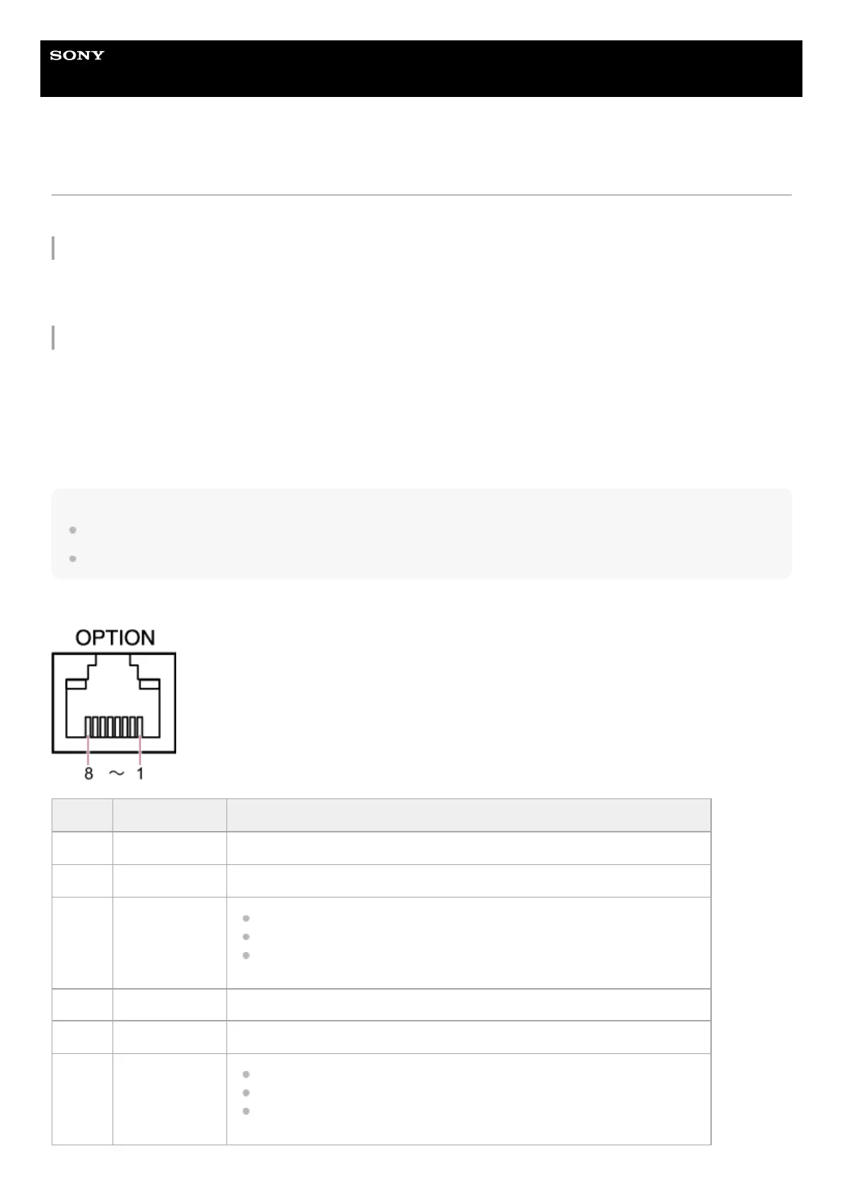
OPTION connector pin specifications
Pin No. Signal direction Signal specifications
1 – Open
2 – Open
3
OUT
*1
Green tally lamp output
Low-level output when green tally lamp is lit.
Hi-Z (open-drain output) when green tally lamp is not lit.
4 – GND (Ground)
5 – GND (Ground)
6
OUT
*1
Red tally lamp output
Low-level output when red tally lamp is lit.
Hi-Z (open-drain output) when red tally lamp is not lit.
 Loading...