32
HCD-CL5MD
CD SECTION
Note :
1. CD Block is basically designed to operate without adjustment.
Therefore, check each item in order given.
2. Use YEDS-18 disc (3-702-101-01) unless otherwise indicated.
3. Use an oscilloscope with more than 10MΩ impedance.
4. Clean the object lens by an applicator with neutral detergent
when the signal level is low than specified value with the
following checks.
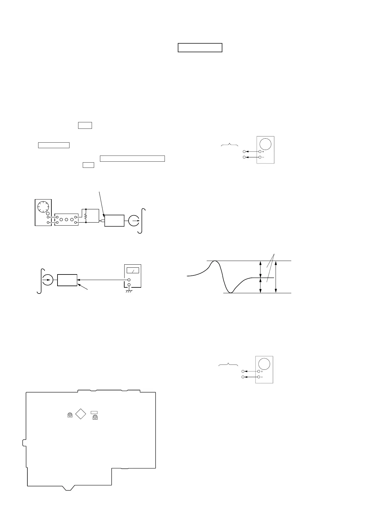
S-Curve Check
Procedure :
1. Connect oscilloscope to TP (FEO).
2. Connect between TP (FEI) and TP (VC) by lead wire.
3. Turn Power switch on.
4. Load a disc (YEDS-18) and actuate the focus search. (In
consequence of open and close the disc tray, actuate the focus
search)
5. Confirm that the oscilloscope waveform (S-curve) is
symmetrical between A and B. And confirm peak to peak level
within 4 ±1 Vp-p.
7. After check, remove the lead wire connected in step 2.
Note : • Try to measure several times to make sure than the ratio
of A : B or B : A is more than 10 : 7.
• Take sweep time as long as possible and light up the
brightness to obtain best waveform.
RF Level Check
Procedure :
1. Connect oscilloscope to TP (RFAC).
2. Turned Power switch on.
3. Load a disc (YEDS-18) and playback.
4. Confirm that oscilloscope waveform is clear and check RF signal
level is correct or not.
5. Measure the RFDC in the same way.
BD (CD) board
Oscilloscope
TP(FEO)
TP(DVC)
symmetry
S-curve waveform
within 4 ±1Vp-p
A
B
Record Level Adjustment
Procedure:
INTRODUCTION
When set to the test mode performed in Tape Speed Adjust-
ment, when the tape is rewound after recording, the “REC memory
mode” which rewinds only the recorded portion and playback is
set.
This “REC memory mode” is convenient for performing this
adjustment. During recording, the input signal FUNCTION will
automatically switch to VIDEO.
(After recording, press the m button without stopping will re-
turn to the position where recording was started.)
1. Press FUNCTION button to select VIDEO. (This step is not
necessary if the above test mode has already been set.)
2. Insert a tape into deck, press the TAPE REC PAUSE/START
button, and then press the Y button to start recording.
3. Mode: Record
4. Mode: Playback
5. Confirm playback the signal recorded in step 2 become adjust-
ment level as follows.
If these levels do not adjustment level, adjust the RV301 (L-CH)
and RV351 (R-CH) on the MAIN board to repeat steps 3 and 4.
Adjustment level:
CN301 playback level: 47.2 to 53.0 mV (–24.3 to –23.3 dB)
Adjustment Location:
[MAIN BOARD]
AF OSC
VIDEO (AUDIO) IN (J101)
315Hz 50 mV (–23.8 dB)
blank tap
CS-123
set
attenuator
600 Ω
recorded
position
level meter
set
main board
CN301
Pin 3 (R-ch)
Pin 1 (L-ch)
CN301
IC301
Record Level (L ch)
RV351
Record Level (R ch)
RV301
TP(RFAC)
TP(DVC)
BD board
oscilloscope