MHC-V41D
15
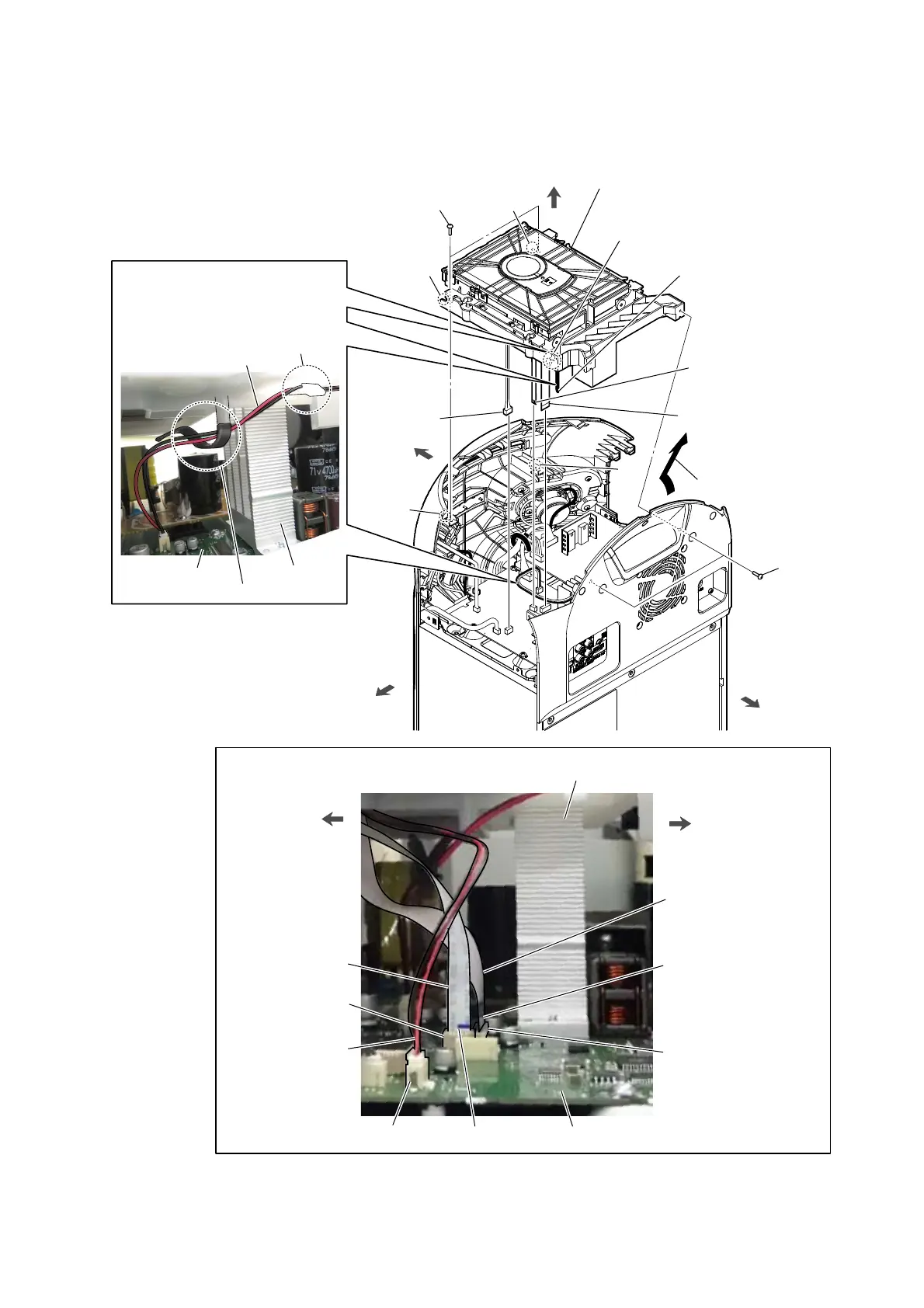
2-7. CDM BLOCK
8 Remove the CDM block
in the direction of the arrow.
3 flexible flat cable (24P) (CN302)
(from optical pick-up block)
(See Fig. F)
6 two screws
(BVTP3 u 8)
front side
DC fan cable
rear side
2 flexible flat cable (5P)
(CN303) (from MS-476 board)
(See Fig. F)
1 OP cable
connector
(CN402)
(See Fig. F)
'&IDQFDEOHVHWWLQJ
:LUHVHWWLQJ
MOTHER board
right side
coating clip
7 two screws
(BVTP3 u 8)
groove
Note 2:
The DC fan cable must not touch
the heat sink.
heat sink
hole
boss
boss
hole
9 CDM block
Note 1:
When installing the CDM block,
align the two bosses and two holes.
–5LJKWYLHZ–
front side
rear side
flexible flat cable (5P)
(from MS-476 board)
CN303
MOTHER board
)LJ)!
terminal side
CN302
CN402
terminal side
flexible flat cable (24P)
(from optical pick-up block)
OP cable
heat sink
top side
4 Remove the DC fan cable
from the coating clip.
5 Remove the DC fan cable
from the groove.
–&'0EORFNERWWRPYLHZ–

 Loading...