MHC-V41D
21
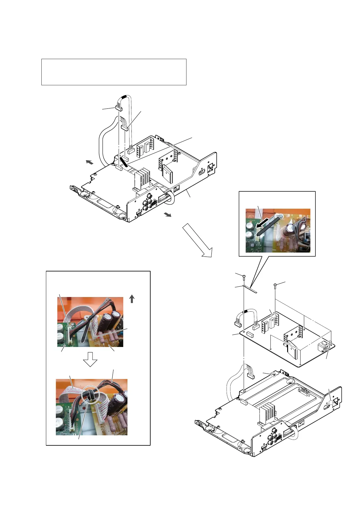
2-14. SMPS BOARD
< Fig. L >
front side
rear side
Installation direction for
the coating clip.
2 SMPS board cable
connector (CN001)
(See Note 1)
4 screw
(BVTP3 u 8)
hole
rib
rib
hole
1 Remove the two cables
from the coating clip.
(See Fig. L)
3 MOTHER board cable
connector (CN6500)
(See Note 1)
4 five screws
(BVTP3 u 8)
chassis block
5 coating clip
6 SMPS board
Note 2:
When installing the SMPS
board, align the two ribs
and two holes.
:LUHVHWWLQJ
SMPS board cable
MOTHER
board
SMPS board
CN6500
MOTHER board cable
coating clip
CN001
front side
–7RSYLHZ–
Note 1: Make sure perform discharge processing before removing the
SMPS board. For the discharge processing method, refer to
“CAPACITOR ELECTRICAL DISCHARGE PROCESS-
ING” on page 5.

 Loading...